Super wide angle optical system

a wide angle optical system and optical system technology, applied in optics, instruments, lenses, etc., can solve the problems of aggravating the distortion of the wide angle lens, and achieve the effects of reducing the size and weight, increasing the definition, and reducing the distortion of the imag

Active Publication Date: 2011-04-26
SAMSUNG ELECTRO MECHANICS CO LTD
View PDF8 Cites 79 Cited by
  • Summary
  • Abstract
  • Description
  • Claims
  • Application Information

AI Technical Summary

Benefits of technology

[0008]An aspect of the present invention provides a super wide angle optical system reduced in size and weight and increased in definition and having a wide angle of view appropriate for image devices used in a surveillance camera installed in various electronic devices or a vehicle camera, thereby reducing distortion of an image.

Problems solved by technology

However, attempts to maintain a wide angle of view for broad image data while reducing the size of the camera have led to aggravation of distortion of the wide angle lens.

Method used


Image

  • Super wide angle optical system
  • Super wide angle optical system
  • Super wide angle optical system

Examples


first embodiment

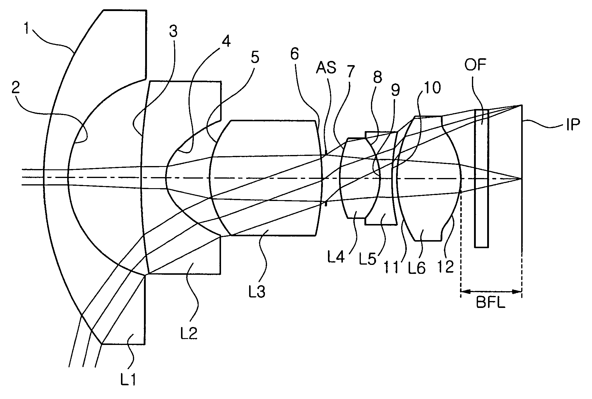
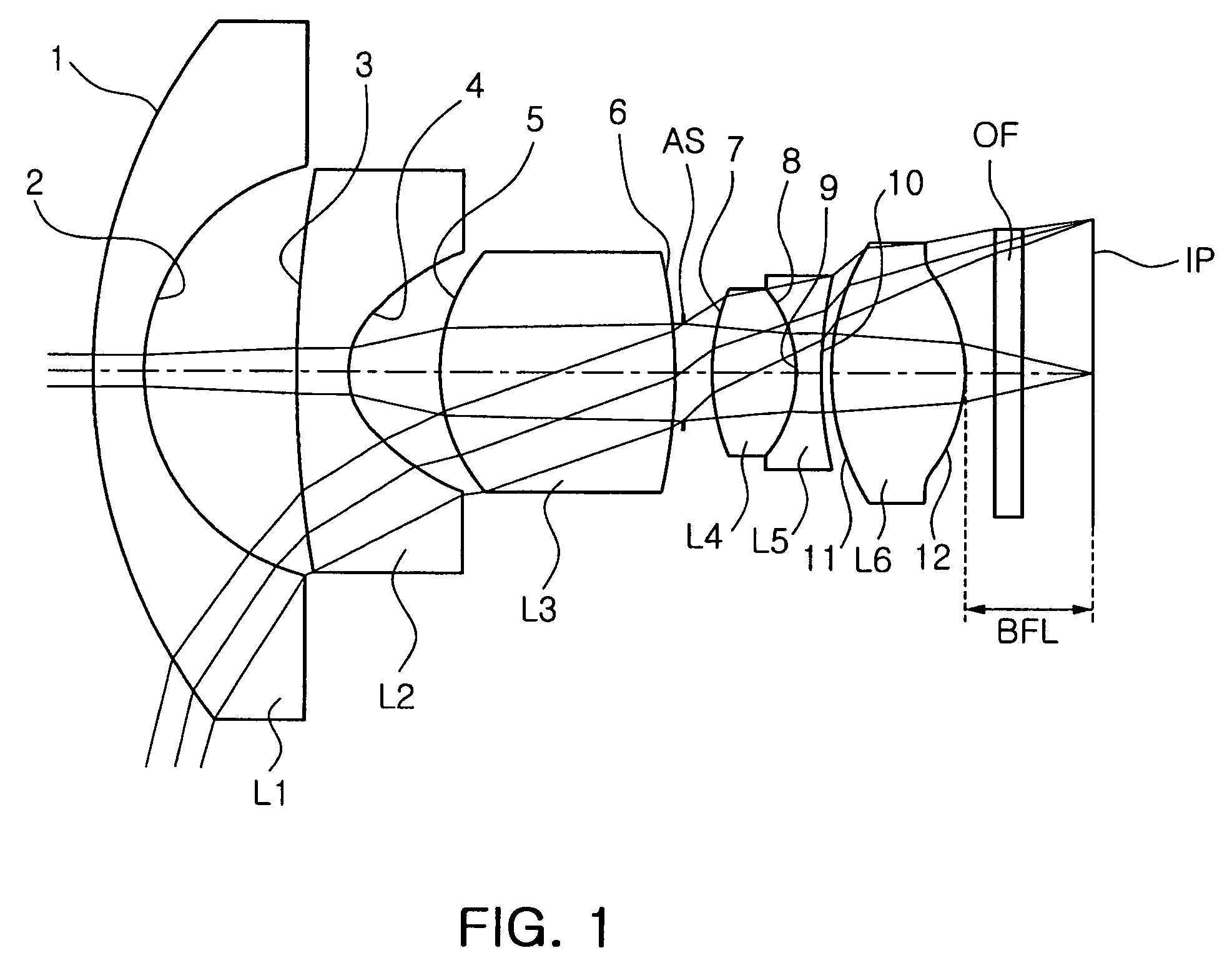
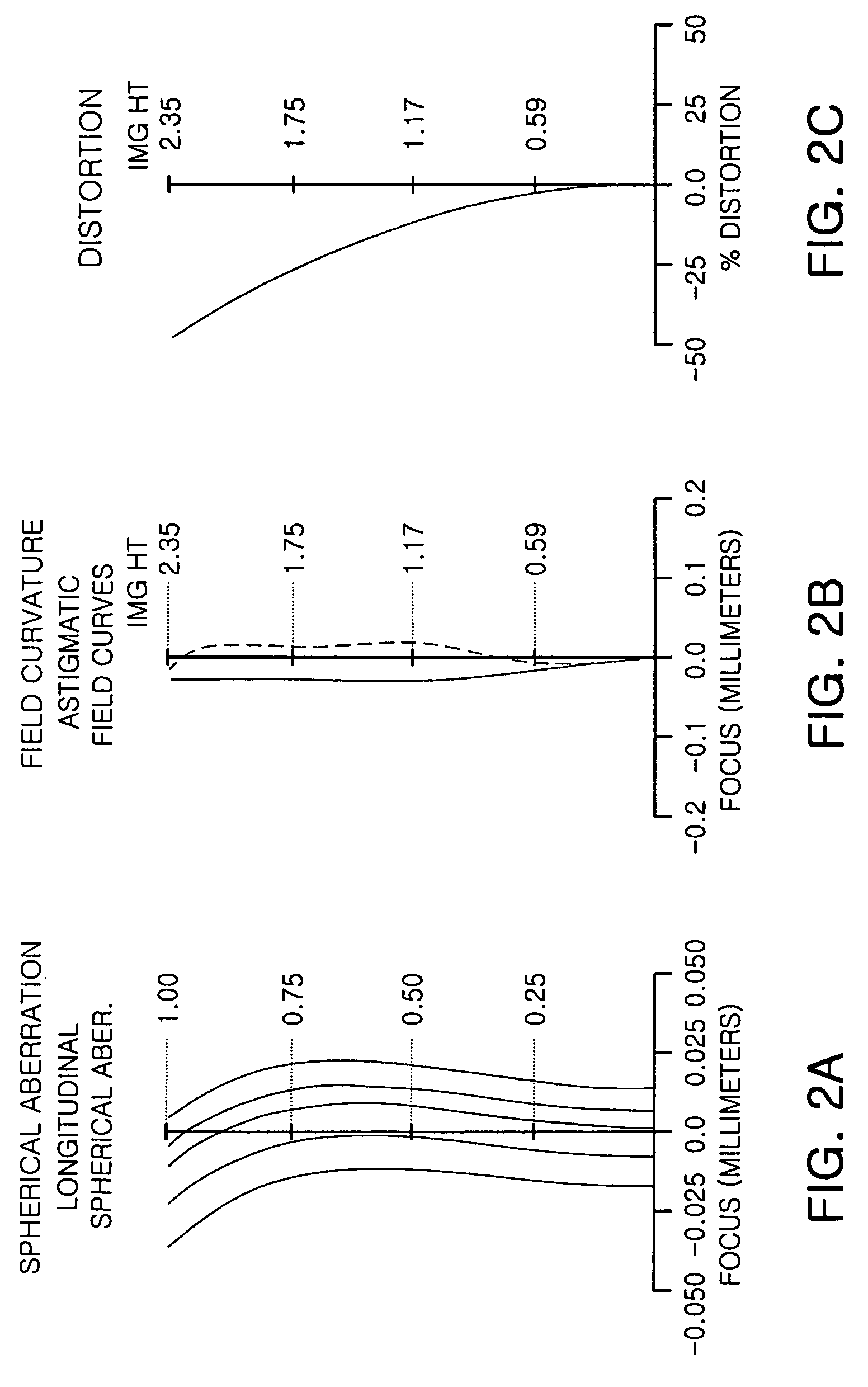
[0080]Table 1 below shows numeral examples of the first embodiment of the present invention.

[0081]In the first embodiment of FIG. 1, an effective focal length is 1.05 mm, a back focal length (BFL) is 1.83 mm, an F-number is 2.0, a total length (TL) is 14.69 mm and an angle of view is 154 degrees.

[0082]Also, a focal length f1 of the first lens L1 is −7.19 mm, a focal length f2 of the second lens L2 is −2.12 mm, a focal length f3 of the third lens L3 is 3.36 mm, a focal length f4 of the fourth lens L4 is 24.94 mm, a focal length f5 of the fifth lens L5 is −4.77 mm, and a focal length f6 of the sixth lens L6 is 2.43 mm.

[0083]Moreover, in this embodiment, as shown in FIG. 1, the fourth lens L4 has both convex surfaces and the fifth lens L5 has both concave surfaces.

[0084]

TABLE 1Sur.Rdndvd18.6460.7001.74444.823.2002.300332.9020.7001.53156.041.0871.39152.9203.4601.74127.76−8.7310.100AS∞0.48173.6431.2001.62060.38−2.1000.4009−2.1000.4001.84723.710 8.8320.15011 2.9561.9801.53156.012 −1.7730....

second embodiment

[0096]Table 3 below shows numeral examples of the second embodiment of the present invention.

[0097]In the second embodiment of FIG. 3, an effective focal length is 1.05 mm, a back focal length (BFL) is 1.87 mm, an F-number is 2.0, a total length (TL) is 15.02 mm and an angle of view is 154 degrees.

[0098]Also, a focal length f1 of the first lens L1 is −7.9 mm, a focal length f2 of the second lens L2 is −2.61, a focal length f3 of the third lens L3 is 3.58 mm, a focal length f4 of the fourth lens L4 is 61.84 mm, a focal length f5 of the fifth lens L5 is −3.52, and a focal length f6 of the sixth lens L6 is 2.3 mm.

[0099]Moreover, in this embodiment, as shown in FIG. 3, the fourth lens L4 has both convex surfaces and the fifth lens L5 has both concave surfaces.

[0100]

TABLE 3Sur.Rdndvd18.0000.7001.74444.823.2722.000314.4340.5501.53156.041.2531.62156.0303.4671.67332.16−3.1240.100AS∞0.89674.6101.1361.62060.38−2.0000.4009−2.0000.4001.84723.710 5.2050.10011 3.6612.1801.53156.012 −1.4640.40013 ...

third embodiment

[0111]Table 5 below shows numeral examples of the second embodiment of the present invention.

[0112]In the third embodiment of FIG. 5, an effective focal length is 1.04 mm, a back focal length (BFL) is 1.81 mm, an F-number is 2.1, a total length (TL) is 15.31 mm and an angle of view is 156 degrees.

[0113]Also, a focal length f1 of the first lens L1 is −6.14 mm, a focal length f2 of the second lens L2 is −2.22, a focal length f3 of the third lens L3 is 3.24 mm, a focal length f4 of the fourth lens L4 is 16.29 mm, a focal length f5 of the fifth lens L5 is −4.76 mm, and a focal length f6 of the sixth lens L6 is 2.31 mm.

[0114]Moreover, in this embodiment, as shown in FIG. 5, the fourth lens L4 has both convex surfaces and the fifth lens L5 has both concave surfaces.

[0115]

TABLE 5Sur.Rdndvd110.1500.7601.74444.823.0502.511322.3540.5001.53156.041.1120.97452.7063.9831.75527.56−9.3810.233AS∞0.55573.6811.1421.62060.38−1.9540.4609−1.9540.4601.75527.510 5.4470.10011 2.8292.2821.53156.012 −1.5560.4...


PUM


Abstract

There is provided a super wide angle optical system including, arranged about an optical axis: a first lens having a negative refractive power and having a meniscus shape with a convex object-side surface; a second lens having a negative refractive power and having a meniscus shape with a convex object-side surface; a third lens having a positive refractive power and having both convex surfaces; a fourth lens having a positive refractive power; a fifth lens having a negative refractive power; and a sixth lens having a positive refractive power and having both convex surfaces.

Description

CROSS-REFERENCE TO RELATED APPLICATIONS[0001]This application claims the priority of Korean Patent Application No. 2008-31815 filed on Apr. 4, 2008, in the Korean Intellectual Property Office, the disclosure of which is incorporated herein by reference.BACKGROUND OF THE INVENTION[0002]1. Field of the Invention[0003]The present invention relates to a super wide angle optical system, and more particularly, to a super wide angle optical system reduced in size and weight and increased in definition to be employed in cameras for a mobile phone terminal, computer and vehicle while capable of obtaining broad image data.[0004]2. Description of the Related Art[0005]In general, a mobile communication terminal, a computer, a lap top computer and a vehicle have a camera installed therein to display or photograph image data. With slimmer mobile communication terminals or smaller-sized computers or laptops, cameras are required to be reduced in size and weight and exhibit high image quality. Also...

Claims


Application Information

Patent Timeline
Patent Type & Authority Patents(United States)
IPC IPC(8): G02B9/62G02B13/18G02B13/02
CPCG02B9/62G02B13/0045G02B13/04G02B13/006G02B13/06G02B9/00G02B13/18
Inventor JUNG, PHIL HOYI, MOON DO
Owner SAMSUNG ELECTRO MECHANICS CO LTD
Why Eureka
Try Eureka