

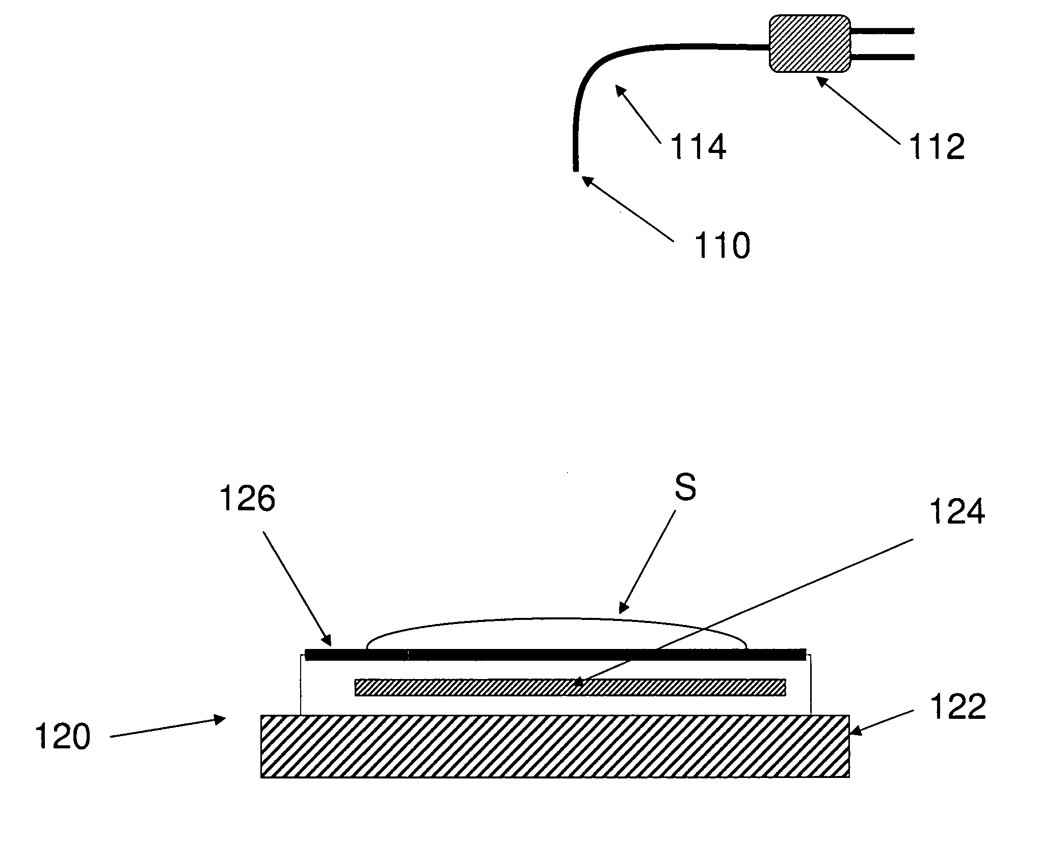
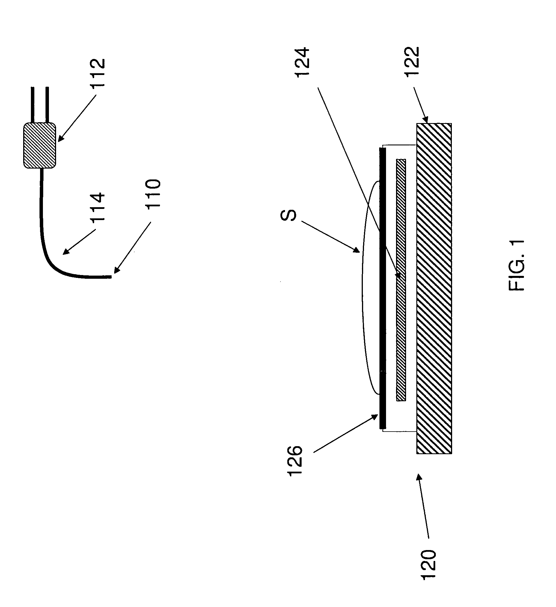
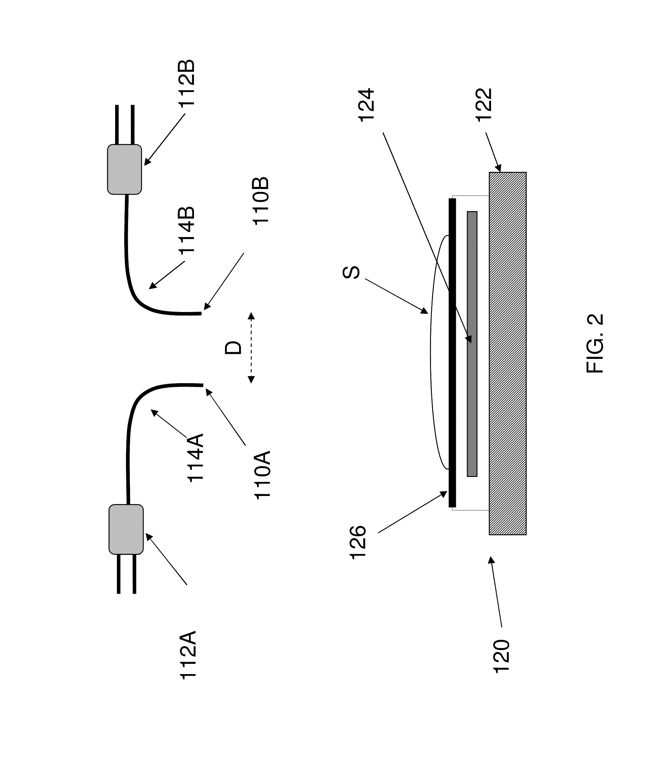
Contact microscope using point source illumination
a technology of point source illumination and microscope, which is applied in the field of contact microscope using point source illumination, can solve the problems of increasing the cost and complexity of the microscope, challenging the faithful drawing and taking measurements of what the amateur sees, and affecting the operation of the microscope by amateurs, so as to achieve less expensive, flexible and robust, and easy to use
- Summary
- Abstract
- Description
- Claims
- Application Information
AI Technical Summary
Benefits of technology
Problems solved by technology
Method used
Image

Examples
Embodiment Construction
[0028]The embodiments of the invention and the various features and advantageous details thereof are explained more fully with reference to the non-limiting embodiments that are illustrated in the accompanying drawings and detailed in the following description. It should be noted that the features illustrated in the drawings are not necessarily drawn to scale. Descriptions of well-known components and processing techniques are omitted so as to not unnecessarily obscure the embodiments of the invention. The examples used herein are intended merely to facilitate an understanding of ways in which the embodiments of the invention may be practiced and to further enable those of skill in the art to practice the embodiments of the invention. Accordingly, the examples should not be construed as limiting the scope of the embodiments of the invention.
[0029]Microscopes are important tools to visualize objects too small or translucent for the human eye to see. Optical microscopes use lenses to ...
PUM
 Abstract
Description
Claims
Application Information