
Electronic control unit and waterproof case

a technology of electronic control unit and waterproof case, which is applied in the direction of electrical apparatus casing/cabinet/drawer, separation process, instruments, etc., can solve the problem of not being able to reliably protect the respiratory filter, and achieve the effect of greater flexibility

Active Publication Date: 2011-05-03
HITACHI ASTEMO LTD
View PDF16 Cites 70 Cited by
  • Summary
  • Abstract
  • Description
  • Claims
  • Application Information

AI Technical Summary

Benefits of technology

[0010]The present invention has been made in view of the above problems, and it is an object of the present invention to provide an electronic control unit having a respiratory filter in a waterproof case. In the electronic control unit, the respiratory filter can be reliably protected during high-pressure cleaning or the like without restricting the mounting direction, posture, or location of such electronic control unit when it is attached in an engine room or the like.
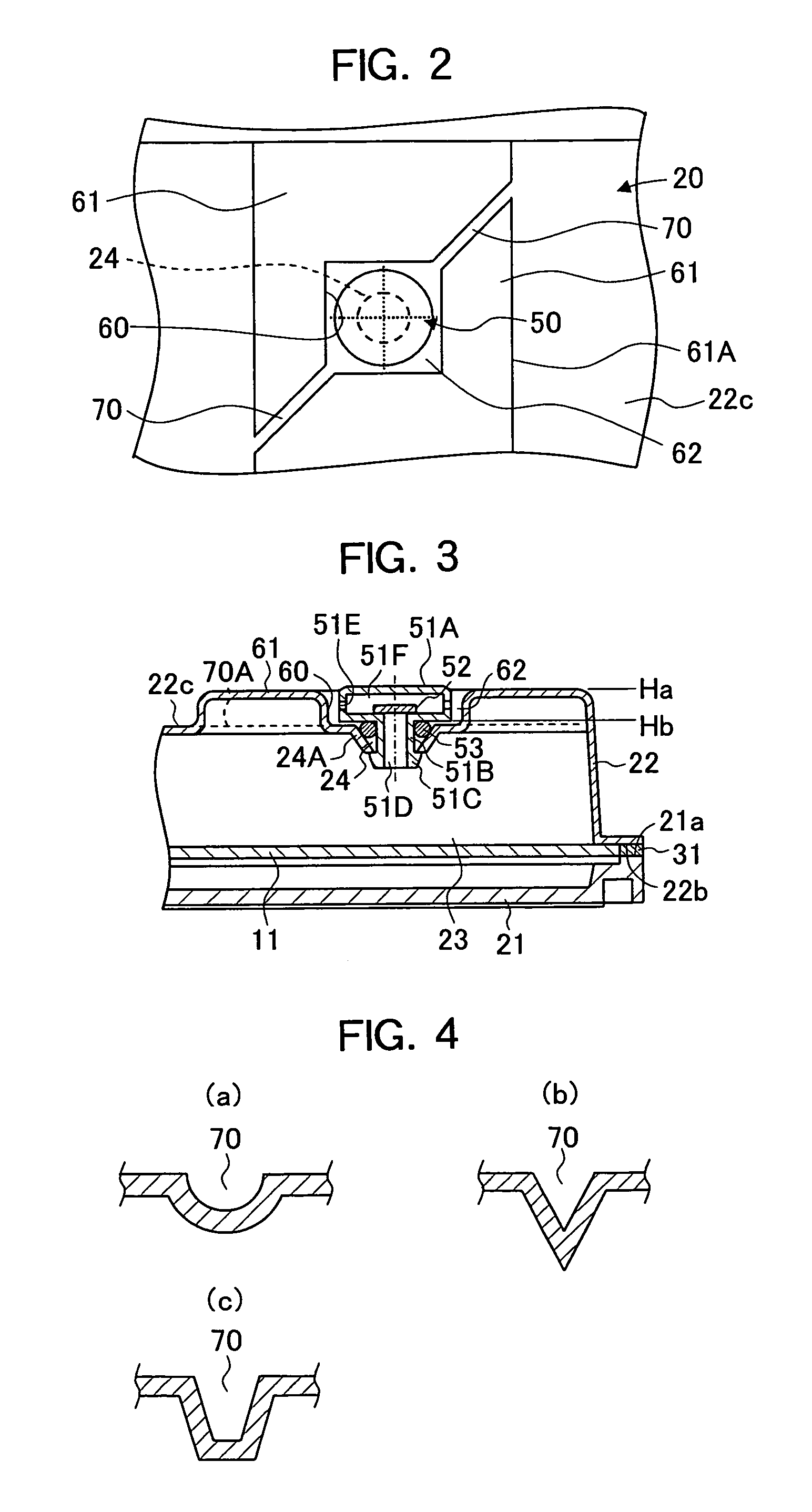
[0020]Since the electronic control unit of the present invention includes such concave portions for drainage or for stagnation prevention positioned in a diagonal or radial manner, corrosion of a waterproof filter or an O-ring due to water or foreign matter is suppressed and the mounting direction, posture, or location in an engine room is not restricted, thereby advantageously offering greater flexibility when mounting the electronic control unit.
[0021]Further, since crooked portions, labyrinthine portions, or inclined portions are provided within the concave portions extending from the respiratory filter side to side surfaces of the case, there is an advantage that a jet used during high-pressure cleaning or the like is prevented from coming into direct contact with the respiratory filter.

Problems solved by technology

Further, providing such channel portion for drainage raises a possibility that a jet used during high-pressure cleaning would come into direct contact with the respiratory filter, thereby resulting in failure to reliably protect the respiratory filter during high-pressure cleaning or the like.

Method used


Image

  • Electronic control unit and waterproof case
  • Electronic control unit and waterproof case
  • Electronic control unit and waterproof case

Examples


Embodiment Construction

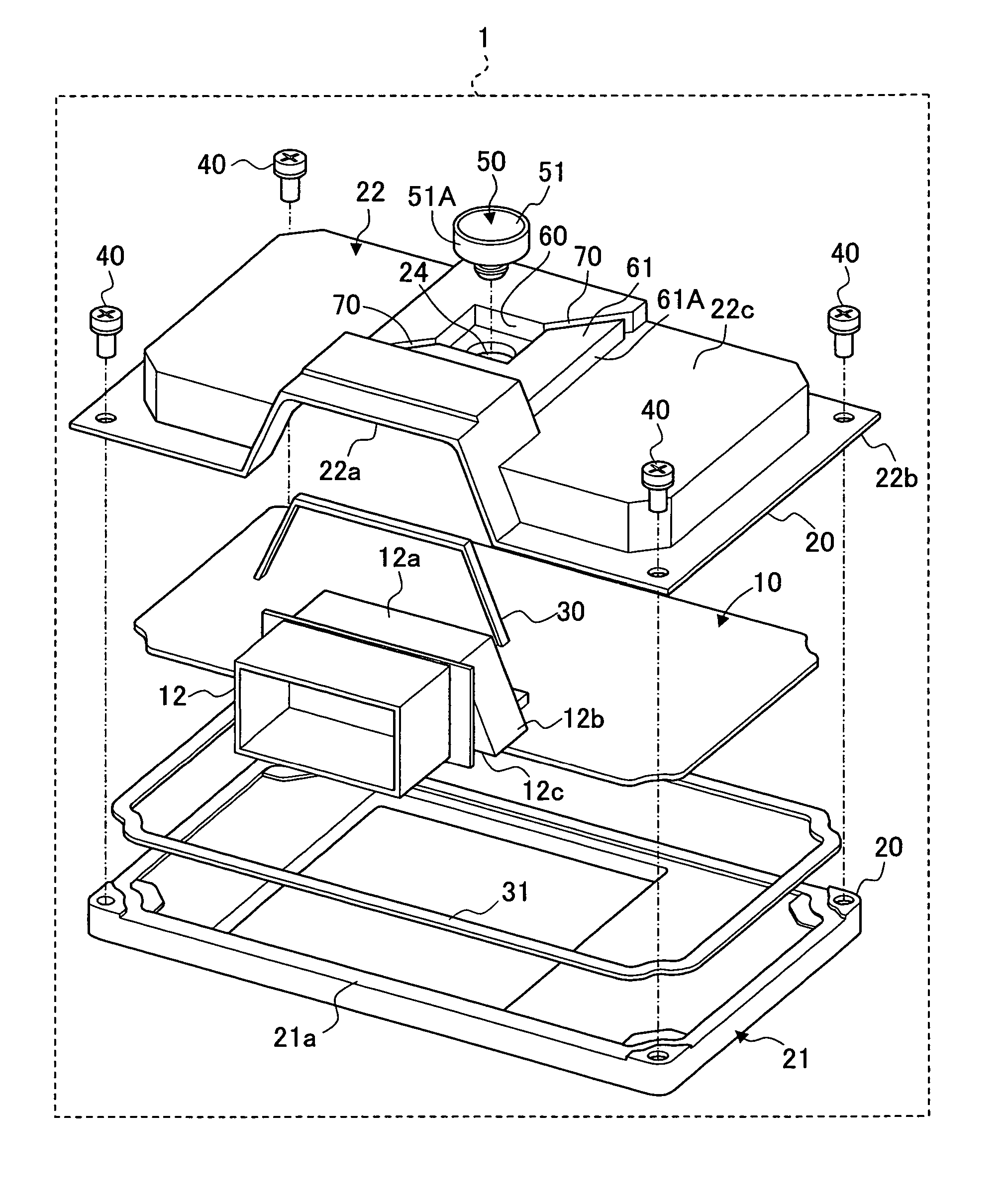
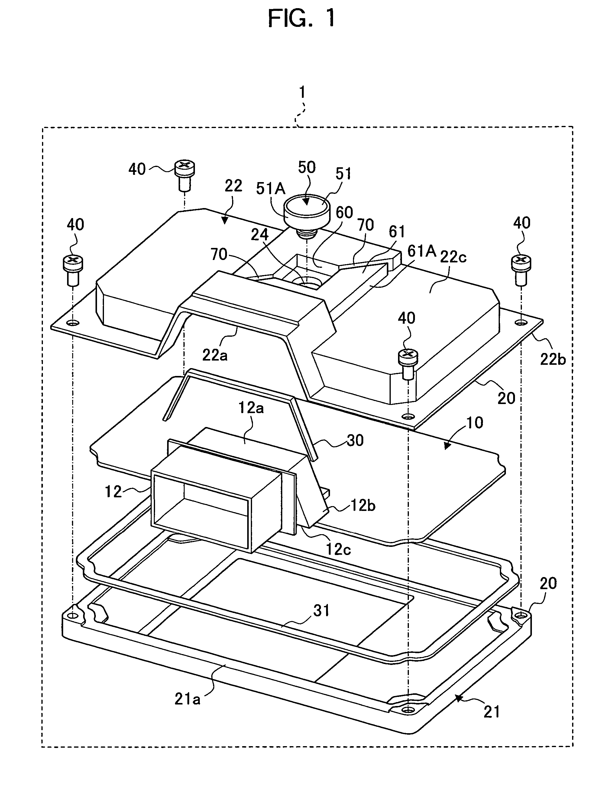
[0031]While preferred embodiments for realizing an electronic control unit of the present invention will be hereafter described in detail, the present invention is not limited to the following embodiments.

[0032]An embodiment of an electronic control unit and waterproof case according to the present invention will be described with reference to FIG. 1 to FIG. 4.

[0033]An electronic control unit 1 of the present embodiment includes a printed-circuit board 10 on which electronic components (not shown), a connector 12, and the like are mounted, and a waterproof case 20 in which the printed-circuit board 10 is housed.

[0034]The waterproof case 20 includes a case body 21 made by die-casting and a cover 22 that is made by die-casting or that is a press-molded article for sealing an opening of the case body 21. The cover 22 has a connector-setting opening 22a having a shape similar to the shape of the connector 12 for receiving the connector 12 mounted on the front end portion of the printed-...


PUM

PropertyMeasurementUnit
thicknessaaaaaaaaaa
shapeaaaaaaaaaa
perimeteraaaaaaaaaa

Abstract

An electronic control unit has a respiratory filter mounted on a waterproof case. Raised protective walls formed in the case surround the portion of the case at which the respiratory filter is arranged. At least two concave portions are provided for drainage that each extend through different positions of the protective walls.

Description

BACKGROUND OF THE INVENTION[0001]1. Field of the Invention[0002]The present invention relates to an electronic control unit and a waterproof case. In particular, it relates to an electronic control unit and a waterproof case, the electronic control unit having a printed-circuit board housed in the waterproof case provided with a respiratory filter.[0003]2. Background Art[0004]As a vehicle-mounted electronic control unit mounted at a site that can be splashed with water in an engine room or the like, an electronic control unit having a printed-circuit board housed in a waterproof case to which a respiratory filter for allowing air to flow into and out of the waterproof case is attached is known (Patent Documents 1 and 2, for example).[0005]In order to prevent a pressure jet from coming into direct contact with the respiratory filter during high-pressure cleaning of an engine room or the like, in one known example, a device is provided with a waterproof case in which a concave portion...

Claims


Application Information

Patent Timeline
Patent Type & Authority Patents(United States)
IPC IPC(8): H05K5/00
CPCH05K5/0052H05K5/0213H05K5/068Y10T137/0396Y10T137/2098H05K5/0216
Inventor SHIGYO, TOSHIKAZUNOZAWA, KAZUNORI
Owner HITACHI ASTEMO LTD
Learn More