Card edge connector with a fastener with a detent portion with a snap-fitting surface

a card edge connector and fastener technology, applied in the direction of coupling device connection, engagement/disengagement of coupling parts, electrical apparatus, etc., can solve the problems of disengagement of electronic cards, inconvenient use, and accidental touching of external components,

Inactive Publication Date: 2011-05-10
LOTES
View PDF9 Cites 18 Cited by
  • Summary
  • Abstract
  • Description
  • Claims
  • Application Information

AI Technical Summary

Benefits of technology

[0012]An objective of the present invention, which is an improvement made on the above-mentioned technical solution, is to provide a card edge connector with a card-disengagement-preventing function that is capable of preventing disengagement of an electronic card more effectively.
[0014]As compared to the prior art, the card edge connector with a card-disengagement-preventing function of the present invention has the following benefits:

Problems solved by technology

However, during the process of assembling different electronic components, if the external component has already been assembled onto the receptacle, then the external component may sometimes been touched accidentally when other assembling steps are being performed.
Due to lack of the clearance that allows for rotation of the ear clip a12, the ear clip a12 is unable to rotate towards the central perpendicular line but only able to rotate away from the central perpendicular line, so it is still likely to cause disengagement of the electronic card “b” from the receptacle “a”.
In summary, the conventional receptacle “a” is not the optimal technical solution for fixing the electronic card “b”.

Method used


Image

  • Card edge connector with a fastener with a detent portion with a snap-fitting surface
  • Card edge connector with a fastener with a detent portion with a snap-fitting surface
  • Card edge connector with a fastener with a detent portion with a snap-fitting surface

Examples


Embodiment Construction

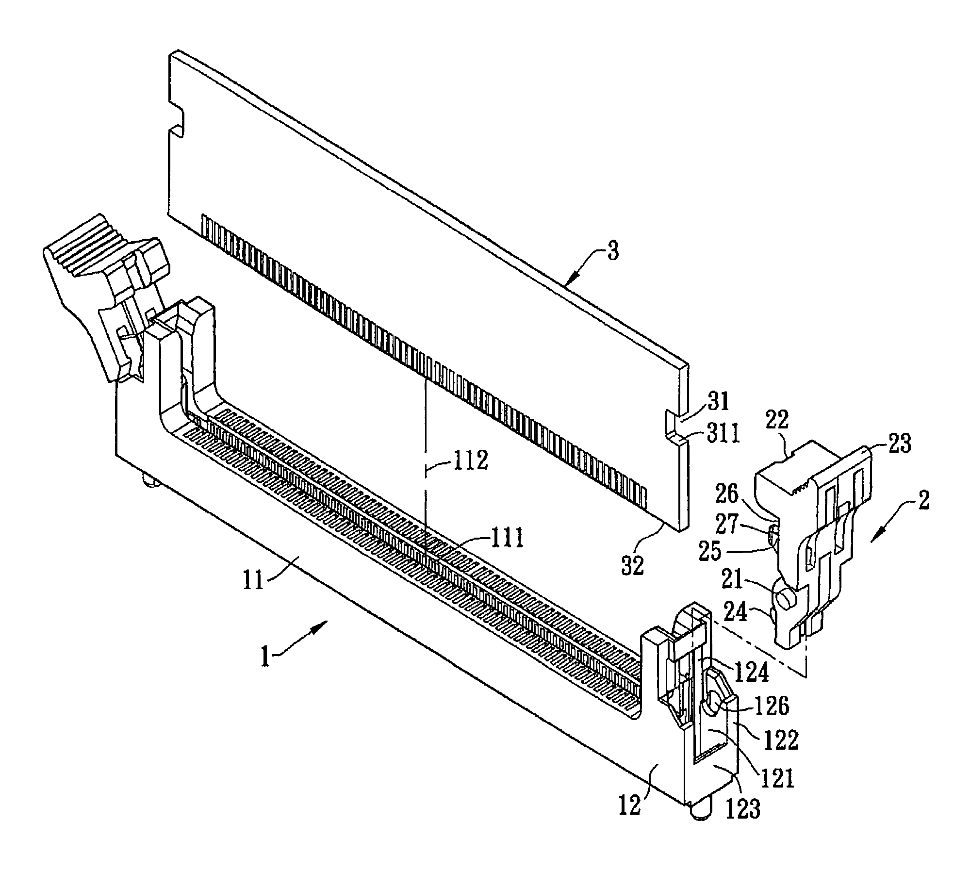
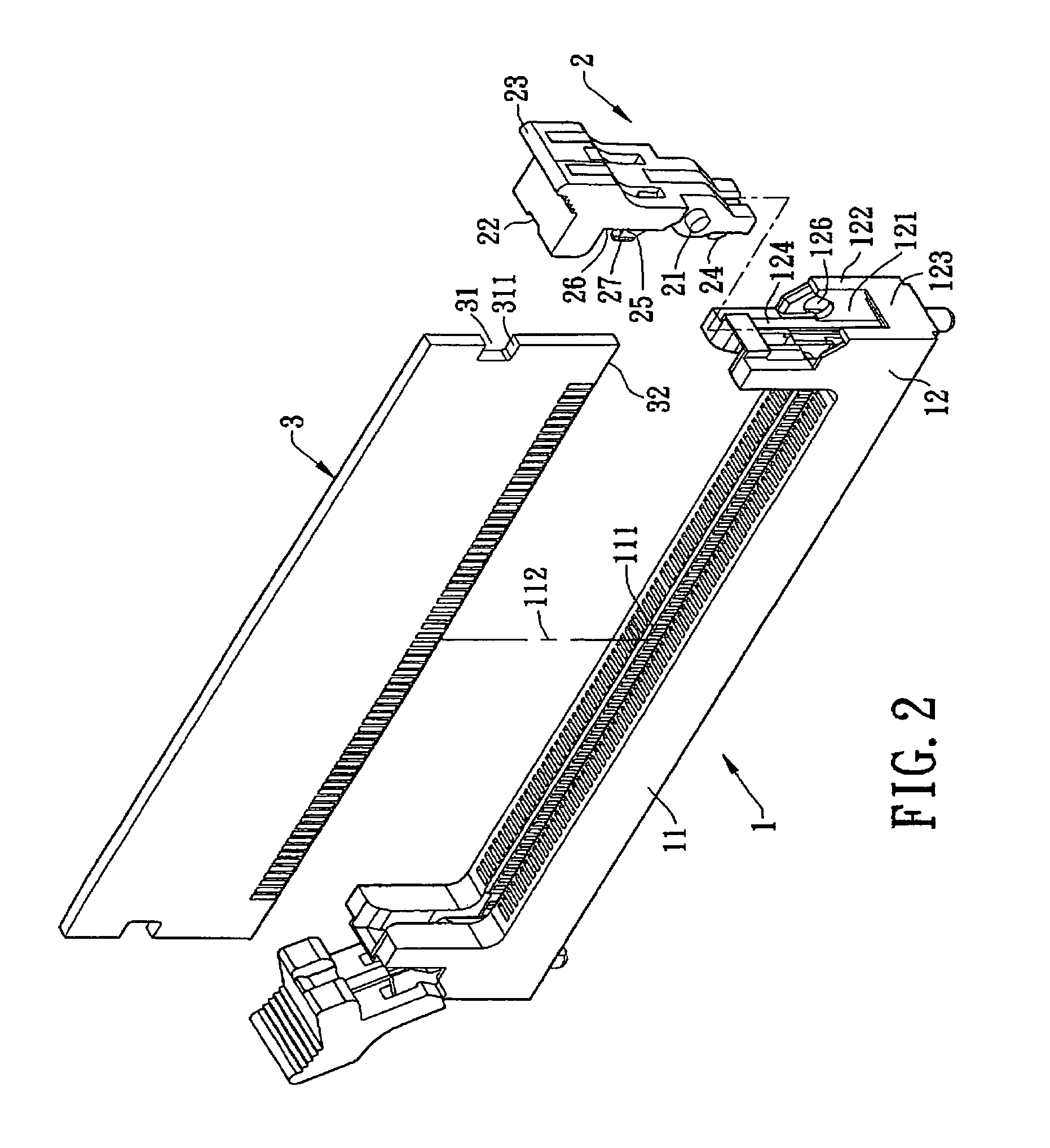
[0034]Hereinafter, the card edge connector with a card-disengagement-preventing function according to the present invention will be further described with reference to the attached drawings and embodiments thereof.

[0035]Referring to FIGS. 2 to 4, a first embodiment of the card edge connector with a card-disengagement-preventing function of the present invention is shown therein. The card edge connector with a card-disengagement-preventing function comprises an electrical receptacle 1 and two fasteners 2.

[0036]The electrical receptacle 1, which is made of an insulation material such as a plastic material, allows for an electronic card 3 to be inserted therein, and has a generally cuboidal base 11 and two tower portions 12.

[0037]The base 11 has a slot 111, which is open upwards, in a central portion thereof for the electronic card 3 to be inserted therein. Further, the base 11 has a central perpendicular line 112.

[0038]Each of the tower portions 12, which is formed at one lateral end ...


PUM


Abstract

The card edge connector includes: an electrical receptacle formed with an abutting surface; two fasteners pivoted to the electrical receptacle, wherein each of the fasteners is formed with a snap-fitting surface that makes contact with the fastened surface to form a fastening area, the fastening area has a contact point that is closest to a central perpendicular line of the electrical receptacle, and the contact point has a first distance from the central perpendicular line; and wherein each of the fasteners is provided with an abutting portion, and when the abutting portion abuts against the abutting surface correspondingly, an abutting area is formed which has an abutting point that is closest to the central perpendicular line of the electrical receptacle, and the abutting point has a second distance from the central perpendicular line that is less than the first distance.

Description

BACKGROUND OF THE INVENTION[0001]1. Field of the Invention[0002]The present invention relates to a card edge connector with a card-disengagement-preventing function, and in particular, to a card edge connector with a card-disengagement-preventing function that is adapted to electrically connect an electronic card to a circuit board.[0003]2. Description of Related Art[0004]A conventional receptacle comprises a body for an external component (e.g., a memory chip) to be inserted therein. The body is formed with two rotary holes at two ends thereof respectively. At two ends of the body, two ear clips are pivoted respectively, each of which is provided with two rotary shafts and a detent portion. Each of the rotary shafts is pivoted into a corresponding one of the rotary holes, and the detent portion is fastened to the external component for purpose to fix the external component.[0005]However, during the process of assembling different electronic components, if the external component has...

Claims


Application Information

Patent Timeline
Patent Type & Authority Patents(United States)
IPC IPC(8): H01R13/62
CPCH01R12/7029H01R12/721H01R13/6273
Inventor ZENG, XIAN JUWANG, YONG FU
Owner LOTES
Why Eureka
Try Eureka