Medical pressure charging control device

A technology of control devices and control parts, which is applied in the field of medical equipment, can solve the problems of locking function failure, small capacity, and inability to meet large capacity, etc., and achieve the effect of quick pressure maintaining performance and convenient structure

Active Publication Date: 2017-06-30
MICRO TECH (NANJING) CO LTD
View PDF7 Cites 5 Cited by
  • Summary
  • Abstract
  • Description
  • Claims
  • Application Information

AI Technical Summary

Problems solved by technology

Due to the different design structures, the existing problems are also different. All structures need to use human fingers to realize the thread engagement and unlocking functions: the eccentric structure requires a second person to reach out to help to successfully complete the negative pressure operation; the lever type The locking function of the structure has the risk of failure under negative pressure (that is, the negative pressure state cannot be stably formed); the oblique wedge structure requires the thumb and index finger to act at the same time to perform negative pressure operations when drawing negative pressure, although this structure can be completed in one go The actions of releasing, pumping, and locking, but due to the structural arrangement, its capacity is relatively small, which cannot meet the market's demand for large capacity

Method used


Image

  • Medical pressure charging control device
  • Medical pressure charging control device
  • Medical pressure charging control device

Examples


Embodiment 1

[0029] This embodiment discloses a medical inflation control device, which includes an outer tube and a threaded push rod inside the outer tube, and is characterized in that a movable caliper including two pliers arms and a caliper control member connected with the movable caliper are arranged inside the outer tube , and a control member connected to the caliper control member; the control member can move between a first position and a second position;

[0030] When the control part moves from the second position to the first position, the control part drives the caliper control part to move to the locking position, thereby pushing the two arms of the movable caliper to hold the threaded push rod tightly, and realize the locking of the threaded push rod;

[0031] When the control member moves from the first position to the second position, the control member drives the caliper control member to move to the release position, thereby pushing the two arms of the movable caliper to...

Embodiment 2

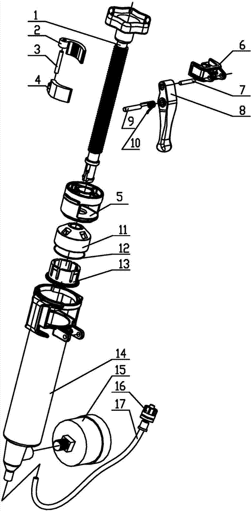
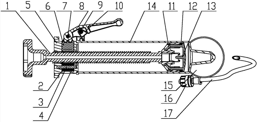
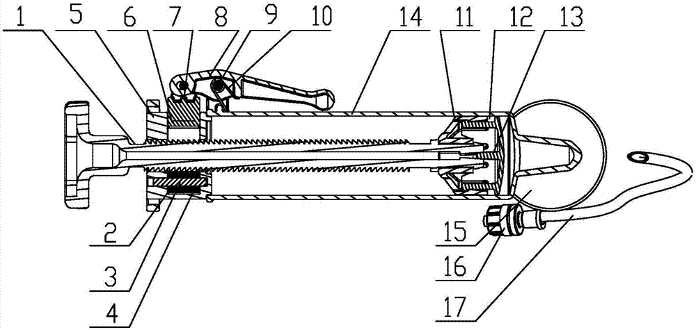
[0041] Such as figure 1 , Figure 2a , Figure 2b and image 3 , a medical inflation control device provided in this embodiment, including a threaded push rod 1, a first lock nut piece 2, a pin shaft 3, a second lock nut piece 4, a fixed seat 5, a movable block 6, a head end Pin 7, lever 8, middle pin 9, torsion spring 10, piston seat 11, O-ring 12, piston cap 13, transparent outer tube 14, pressure gauge 15, joint 16 and network pipe 17; A lock nut piece 2 is connected with the second lock nut piece 4; the movable block 6 and the lever 8 are connected by the head pin 7; the torsion spring 10 and the lever 8 are connected by the middle pin 9; finally the pivot pin 3 After the connecting parts are loaded into the fixed seat 5, the threaded push rod 1, the fixed seat 5, the piston seat 11, the O-ring 12, and the piston cap 13 are firmly connected in order and then packed into the transparent outer tube 14; the pin shaft 7 and the pin The connecting parts of the shaft 9 are s...

Embodiment 3

[0051] Such as Figure 9 , the first lock nut piece 2 and the second lock nut piece 4 are each connected to the fixing seat through a pin shaft.


PUM


Abstract

The invention provides a medical pressure charging control device comprising an outer tube and a threaded push rod located within the outer tube. A movable clamp comprising two clamping arms, a clamp control part connected to the movable clamp and a manipulating part connected with the clamp control part are arranged within the outer tube. When the manipulating part moves from a second position to a first position, the manipulating part drives the clamp control part to move to a locking position, thereby pushing the two clamping arms of the movable clamp to hold tightly the threaded push rod and thus realizing locking of the threaded push rod. When the manipulating part moves from a first position to the second position, the manipulating part drives the clamp control part to move to a release position, thereby pushing the two clamping arms of the movable clamp to loosen the threaded push rod and thus realizing release of the threaded push rod.

Description

technical field [0001] The invention relates to the field of medical equipment, in particular to a medical inflation control device. Background technique [0002] The medical balloon pressure pump is suitable for balloon dilatation catheters, which can be used for filling and shrinking the balloons, and can be used for dilating operations on the narrow part of the human cavity. During expansion, the balloon pressure pump needs to be used to inject liquid, pressurize and monitor the pressure of the balloon. When drawing negative pressure, it is very convenient to realize the single-person pumping and locking action. At present, the conventional disposable medical balloon pressure pumps in clinical use are basically thread push type, but the structure of the engagement and unlocking of the screw and the nut is different. The typical engagement and unlocking structures are: eccentric type, lever type, wedge type Wait. Due to the different design structures, the existing probl...

Claims


Application Information

Patent Timeline
Patent Type & Authority Applications(China)
IPC IPC(8): A61M29/04
CPCA61M29/02A61M2205/3331A61M25/10182
Inventor 金鸿雁仇卫勤李常青
Owner MICRO TECH (NANJING) CO LTD
Why Eureka
Try Eureka