Method and apparatus for spinal fixation

a spinal fixation and apparatus technology, applied in the field of medical devices, can solve the problems of interference with the back of the patient's head, injury to the vertebrae and associated connective elements, and inability to stabilize the patient's spine,

Active Publication Date: 2011-05-10
DEPUY SYNTHES PROD INC
View PDF45 Cites 110 Cited by
  • Summary
  • Abstract
  • Description
  • Claims
  • Application Information

AI Technical Summary

Benefits of technology

[0014]In some embodiments, a system for coupling a first superior vertebra of a cervical spine to a second inferior vertebra comprises a fixation device and an elongated tubular device. The fixation device has a distal end and a proximal end. The distal end of the fixation device is configured to extend between the first superior vertebra and the second inferior vertebra. The elongated tubular device is configured to apply the fixation device. The tubular device has a first longitudinal axis and a handle extending along a second longitudinal axis. The first and second longitudinal axes form an angle with respect to each other such that when the elongated tubular device is applied to the cervical spine from a direction above the cervical spine, the fixation device can be applied without interference from the head of the patient.

Problems solved by technology

Additionally, the vertebrae and associated connective elements are subject to injuries, including fractures and torn ligaments and surgical manipulations, including laminectomies.
Notwithstanding the success of the above described devices and methods, there are certain challenges associated with applying the trans-laminar, trans-facet or facet-pedicle (e.g., the Boucher technique) techniques to the cervical portion of the vertebrae.
For example, due to the anatomy of the cervical region and interference due to the back of the head in a trans-facet approach, the fixation device may need to extend along an axis that, when extended, interferes with the back of the patient's head.
As shown, the back of the patient's spine can interfere with the insertion of the fixation device and the various tools needed to insert the fixation device.

Method used


Image

  • Method and apparatus for spinal fixation
  • Method and apparatus for spinal fixation
  • Method and apparatus for spinal fixation

Examples


Embodiment Construction

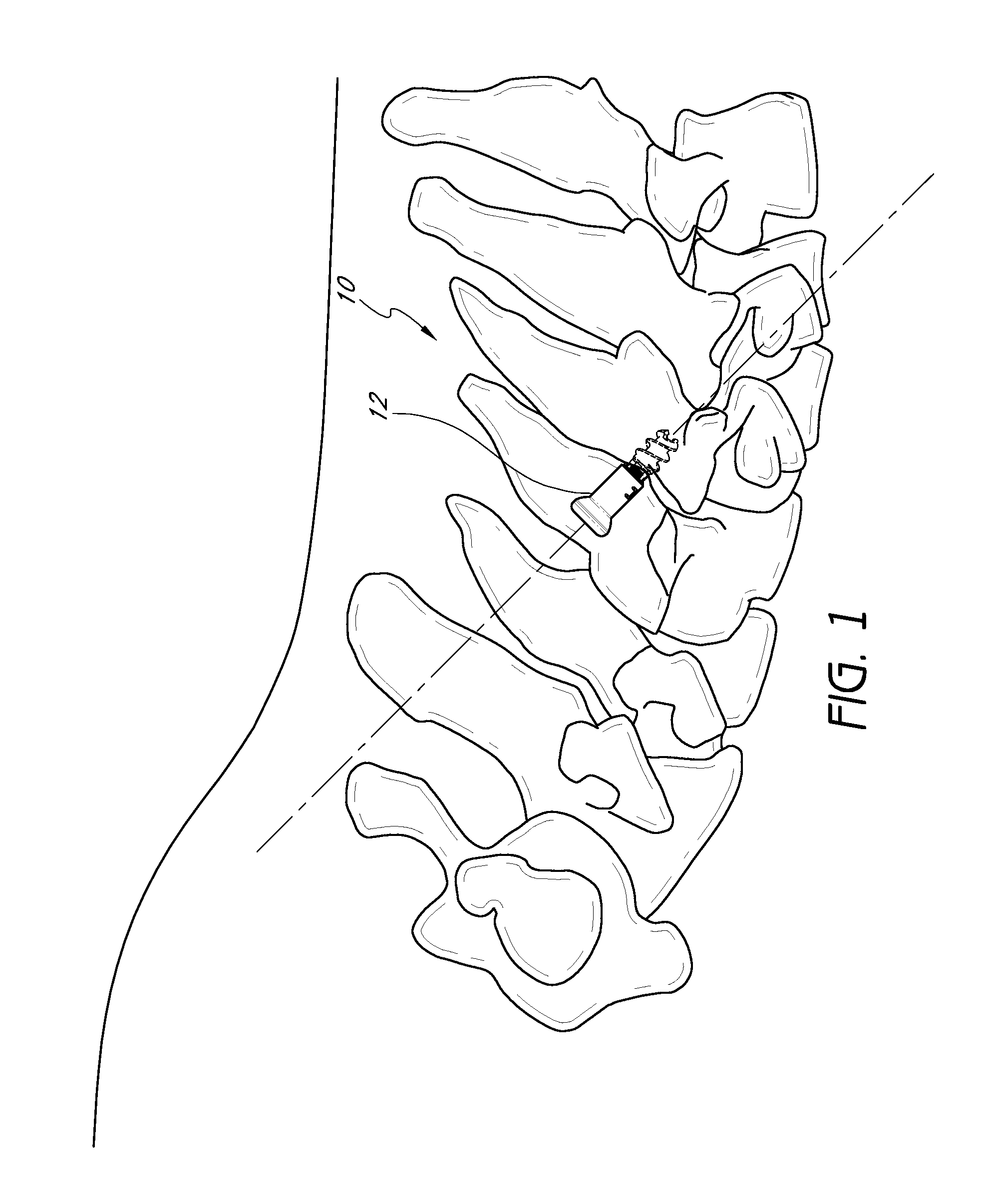
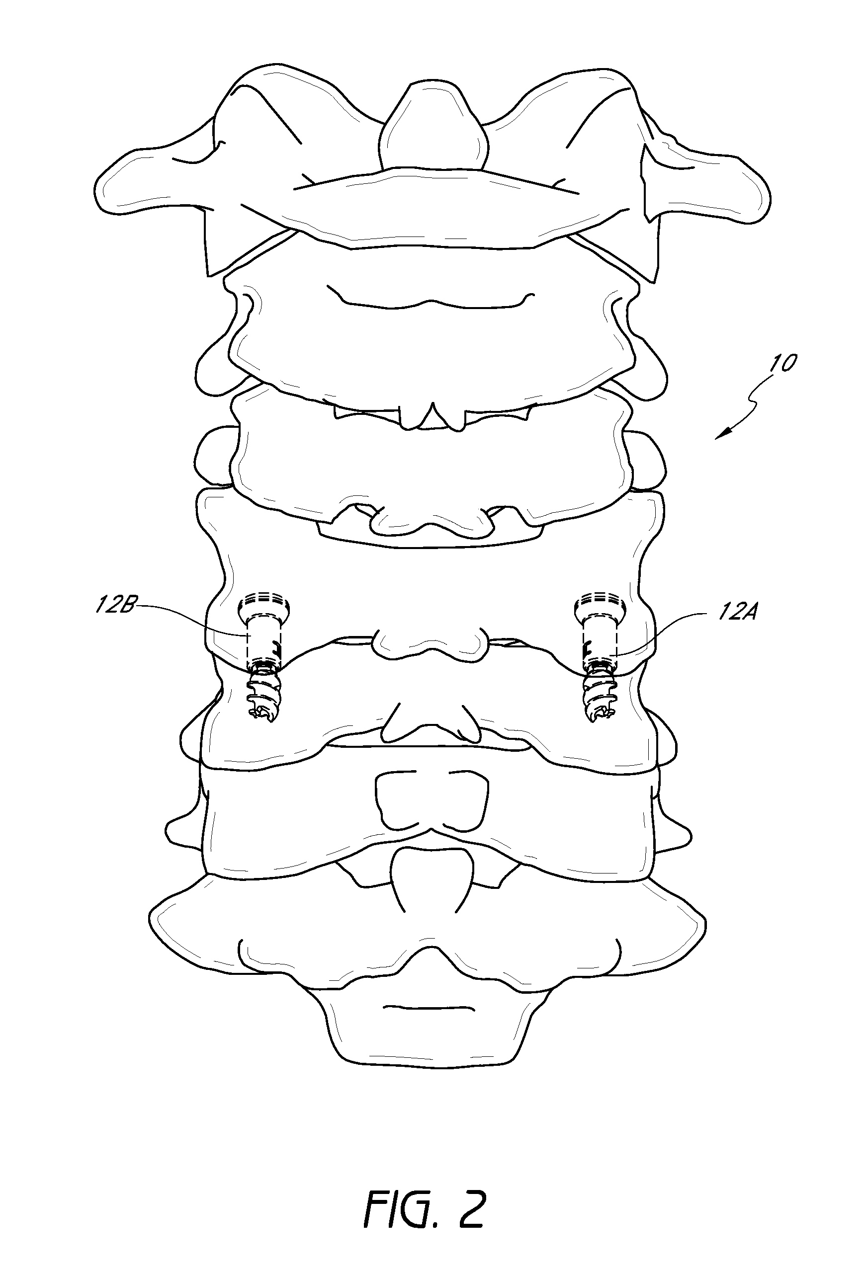
[0120]Referring to FIG. 1, a side elevational view of an exemplary embodiment of the cervical portion of the spine 10 with a fixation device 12 that extends across the facet joint of two adjacent vertebrae (i.e., a trans-facet application) is illustrated. With reference to FIG. 2, a pair of bone fixation devices 12A, 12B can preferably (but not necessarily) be used with substantial bilateral symmetry to secure two adjacent vertebra to each other (In FIGS. 1 and 2 the bone fixation device is highlighted such that the portions hidden by the vertebrae can be seen). In this manner, the adjacent vertebrae of the spine are united together (“fused”) so that motion no longer occurs between the vertebrae. Thus, even in the absence of a stabilizing bar tying pedicle screws to adjacent vertebrae, the fixation devices 12A, 12B can be used to stabilize two vertebrae to each other pending the healing of a fusion. See also U.S. Patent Publication No. 2004 / 0127905, filed Jul. 18, 2003, application ...


PUM


Abstract

Fusion of cervical spinal vertebrae with one or more fixation devices can be accomplished with the described tools and methods. For example, a guidewire introducer can include a tubular introducer cannula and a handle. The handle can be angularly offset from the introducer cannula such that positioning of the introducer on the cervical spine does not interfere with a patient's head. A sheath assembly can include inner and outer sheath bodies and a handle. The handle is angularly offset from the sheath bodies such that the sheath assembly can be applied to the cervical spine without interference to the patient's head. The sheath body can be curved or straight. Various tools such as drills, tapping devices, compression tools, and pin release tools can be applied to the cervical spine through the sheath body to apply the fixation device. The tools can include elongate flexible shafts.

Description

CROSS-REFERENCE TO RELATED APPLICATIONS[0001]This application claims the benefit of U.S. Provisional Patent Application No. 60 / 800,568, entitled “METHOD AND APPARATUS FOR SPINAL FIXATION,” filed on May 15, 2006 and U.S. Provisional Patent Application No. 60 / 794,171, entitled “METHOD AND APPARATUS FOR SPINAL FIXATION,” filed on Apr. 21, 2006.[0002]Also, this application hereby incorporates by reference the above-identified provisional applications, in their entireties.BACKGROUND OF THE INVENTION[0003]1. Field of the Invention[0004]The present application relates to medical devices and, more particularly, to methods and apparatus for spinal stabilization.[0005]2. Description of the Related Art[0006]The human spine is a flexible weight bearing column formed from a plurality of bones called vertebrae. There are thirty three vertebrae, which can be grouped into five regions (cervical, thoracic, lumbar, sacral, and coccygeal). Moving down the spine, there are generally seven cervical vert...

Claims


Application Information

Patent Timeline
Patent Type & Authority Patents(United States)
IPC IPC(8): A61B17/58
CPCA61B17/1757A61B17/7064A61B17/0218A61B17/1655A61B17/1671A61B2017/922A61B17/8861A61B2017/0046A61B2017/00469A61B17/56A61B17/70
Inventor CULBERT, BRAD S.KHOO, LARRYFLOWER, BOB
Owner DEPUY SYNTHES PROD INC
Why Eureka
Try Eureka