Method and system for dynamic power management in wireless local area networks

a wireless local area network and dynamic power management technology, applied in the direction of wireless commuication services, instruments, synchronisation arrangement, etc., can solve the problems of increasing packet collision, reducing overall network throughput, increasing contention for transmission channels, etc., and achieve the effect of improving spatial reus

Active Publication Date: 2011-05-17
NEC CORP
View PDF25 Cites 4 Cited by
  • Summary
  • Abstract
  • Description
  • Claims
  • Application Information

AI Technical Summary

Benefits of technology

The present invention is directed to a system and method that provide improved spatial reuse in a wireless local area network (WLAN) by dynamically tuning an access point's (AP) transmission power on a per-client basis. According to embodiments of the present invention, APs can transmit data packets to a client at the lowest transmission power at which the client can successfully receive the data packets.
According to another embodiment of the present invention, a WLAN includes multiple APs, each servicing multiple clients, and a central controller. Each AP associates each of its clients with a minimum power level. The central controller generates a schedule for transmission at each of multiple transmission power levels for a corresponding transmission time. Based on the schedule, each AP transmits at each of the transmission power levels for the corresponding transmission time. Each AP transmits data packets, at the scheduled transmission power level, to clients associated with a minimum power level that is less than the scheduled power level. Each AP can transmit refinement hints to the central controller, and the central controller can refine the global schedule based on the refinement hints. Each AP can also upgrade the minimum power levels associated with its clients.

Problems solved by technology

Greater overlap of interference and transmission ranges can lead to increased contention for transmission channels and increased packet collisions.
As a result, in a dense deployment of APs for maximal coverage, each AP often operates at sub-optimal performance due to interference from neighboring APs, thereby reducing overall network throughput.
The approach of using non-overlapping transmission channels suffers from a scarcity of non-overlapping channels in the 802.11a / b / g standard, which is commonly used for WLANs.

Method used


Image

  • Method and system for dynamic power management in wireless local area networks
  • Method and system for dynamic power management in wireless local area networks
  • Method and system for dynamic power management in wireless local area networks

Examples


Embodiment Construction

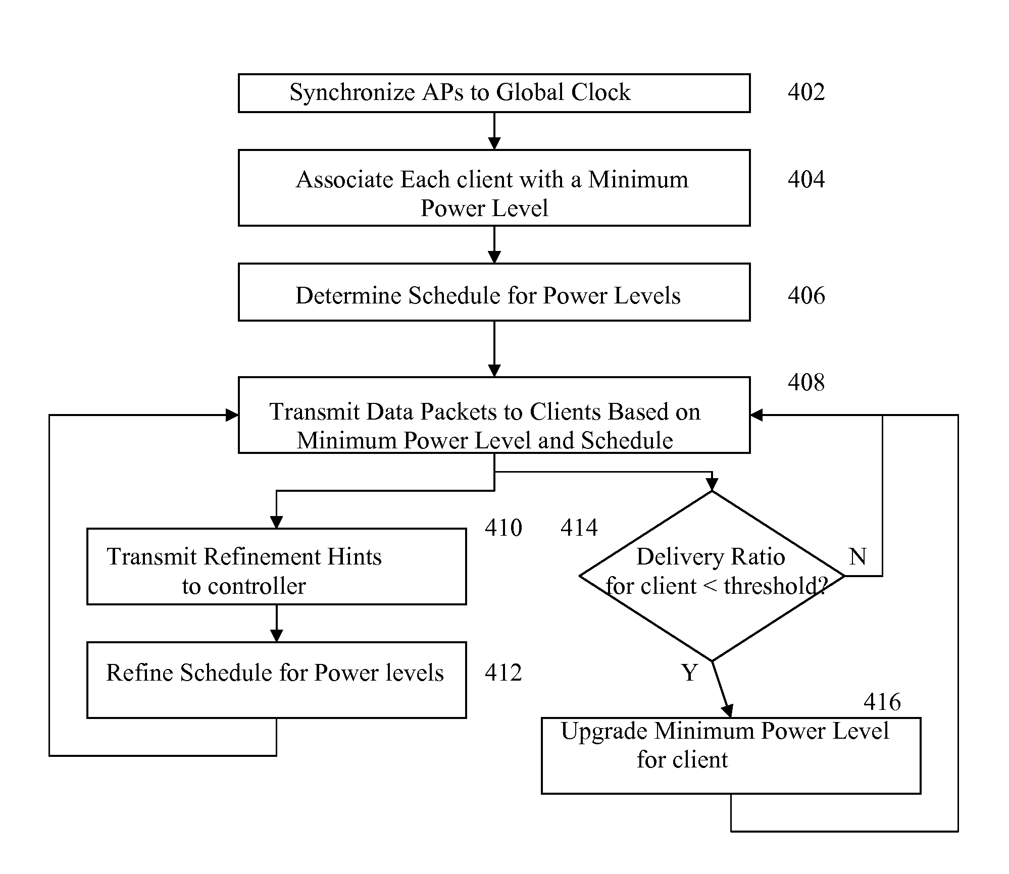
The present invention is directed to improving spatial reuse in a wireless local area network (WLAN) by per-client dynamic power management. Embodiments of the present invention are directed to per-client dynamic power management in a managed WLAN, in which all of access points (APs) are under the same administrative control.

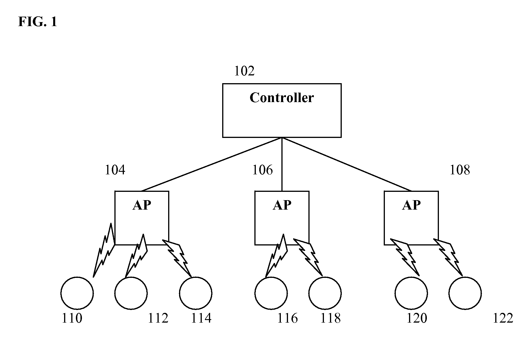
FIG. 1 illustrates an exemplary managed WLAN. As illustrated in FIG. 1, the WLAN included APs 104, 106, and 108, which provide wireless network access to clients 110, 112, 114, 116, 118, 120, and 122. A central controller 102 communicates with each of the APs 104, 106, and 108. The controller 102 can be communicate with to the APs 104, 106, and 108 wiredly or wirelessly, in order to transmit administrative instructions to the APs 104, 106, and 108. The APs 104, 106, and 108 independently schedule and transmit data packets to their respective clients 110, 112, 114, 116, 118, 120, and 122, using a wireless protocol, such as 802.11 a / g / b. The APs 104, 106, and 108 ...


PUM


Abstract

A method and system for improving spatial reuse in a wireless local area network (WLAN) by per-client dynamic power management. Each access point of the WLAN associates each of its clients with a minimum power level. A central controller of the WLAN generates a schedule for transmission at different power levels, and each access point varies its transmission power level based on the schedule. An access point transmits data packets, at the scheduled transmission power level, to clients associated with a minimum power level that is less than the scheduled power level.

Description

BACKGROUND OF THE INVENTIONThe present invention relates to power management in wireless local area networks (WLANs), and more particularly to a dynamic per-client power management in WLANs.Wireless local area network (WLAN) is an important technology, for providing Internet access to users. Managed WLANs refer to deployments in which all access points (APs) are under the same administrative domain. Example of such managed WLANs include small-range corporate networks and campus networks, hot-spot networks, such as T-mobile, and city-wide networks, such as Google's Wifi, MIT's roofnet, and Houston's urban network. In order to provide maximal coverage, such networks often contain multiple APs with overlapping transmission and frequency ranges. While coverage depends on the transmission ranges of the APs, the performance of each AP depends on the inference ranges of neighboring APs. Greater overlap of interference and transmission ranges can lead to increased contention for transmissio...

Claims


Application Information

Patent Timeline
Patent Type & Authority Patents(United States)
IPC IPC(8): G08C17/00H04B7/00H04J3/14H04W4/00H04W52/34H04W52/36H04W56/00H04W84/12
CPCH04W52/34H04W52/367H04W84/12H04W56/00
Inventor KOKKU, RAVIDRANATHNAVDA, VISHNUGANGULY, SAMRAT
Owner NEC CORP
Why Eureka
Try Eureka