X-ray system and method for tomosynthetic scanning

a tomosynthetic and x-ray technology, applied in the field of x-ray system and tomosynthetic scanning, can solve the problems of thermal problems in the x-ray tube, the resolution speed of the x-ray tube is thus limited, and the method is complicated and expensive, so as to achieve less stress on the radiation source and less costly to execute

Active Publication Date: 2011-05-17
SIEMENS HEALTHCARE GMBH
View PDF7 Cites 18 Cited by
  • Summary
  • Abstract
  • Description
  • Claims
  • Application Information

AI Technical Summary

Benefits of technology

[0012]By the use of at least two radiation sources, for the same number of x-ray exposures or emission of the same x-ray dose during a tomosynthetic scan each radiation source must emit only a portion of the x-ray radiation (for example half given two radiation sources) relative to a conventional tomosynthetic x-ray system with one radiation source. The number of projections—thus x-ray exposures that can be generated in a given scan time during the tomosynthetic scan—increases. Therefore the scan speed (thus the time for the complete tomosynthetic scanning) can be distinctly reduced given a corresponding, sufficiently fast detector if the x-ray excitations were the critical time factor. Since each radiation source must emit less radiation, the thermal load of the radiation sources likewise drops relative to a single radiation source. The entire beam power of the x-ray system likewise increases with the number of sources.
[0017]Alternatively, however, different radiation sources can also be arranged as different focal spots on a single anode. A corresponding x-ray tube with a single anode is simpler and less costly to execute.
[0018]As already mentioned, different radiation sources can be configure to emit x-rays of different energies. To implement the dual energy method, each radiation source can be permanently set to a specific energy level of the x-ray power. The single radiation source thus does not need to be continuously switched between different energies. This means significantly less stress for the radiation sources. In connection with an energy-resolving detector, both radiation sources can even be simultaneously excited, and two x-ray images projection exposures with different beam energy can respectively be acquired simultaneously by the detector. The scan time for a dual energy tomosynthetic scan is hereby distinctly reduced. Naturally, as before a switching of the radiation sources over to one location is also conceivable so that one and the same projection acquisition is executed with different energies.

Problems solved by technology

For example, computed tomography (CT), in which an x-ray tube and its opposite detector orbit a patient as an examination subject in order to generate slice exposures of the patient, is hereby a complicated and expensive method.
The resolution speed of the x-ray tubes is thus limited, and a 50° tomosynthetic scan (i.e. panning of the x-ray tube in an angle range of 50°) for the generation of the multiple x-ray images or projection exposures from various viewing directions today takes between ten seconds and one minute.
However, such high image rates can lead to thermal problems in the x-ray tube, not only in the anode but also in the cathode.
The thermal problems arise from the need to transport of the heat away from the anode of the x-ray tube since there less than 1% of the supplied energy is converted into x-ray radiation and more than 99% is converted into heat.
In contrast to CT with a focal diameter of 1 mm on the anode, due to the higher resolution mammography operates with a 0.3 mm focus, for example, which results in a significantly higher energy density and therefore distinctly greater thermal problems in the x-ray tube.

Method used


Image

  • X-ray system and method for tomosynthetic scanning
  • X-ray system and method for tomosynthetic scanning
  • X-ray system and method for tomosynthetic scanning

Examples


Embodiment Construction

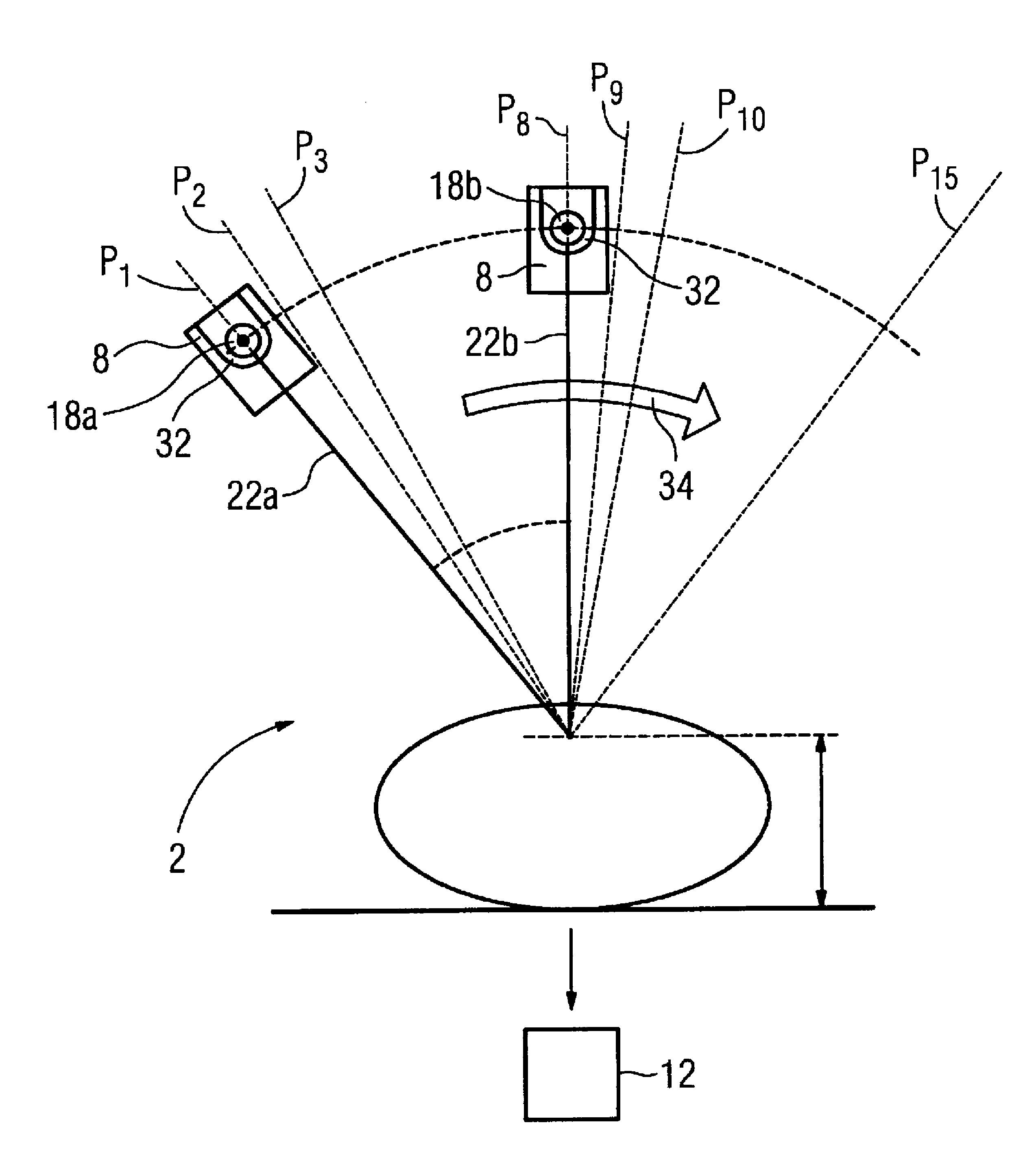
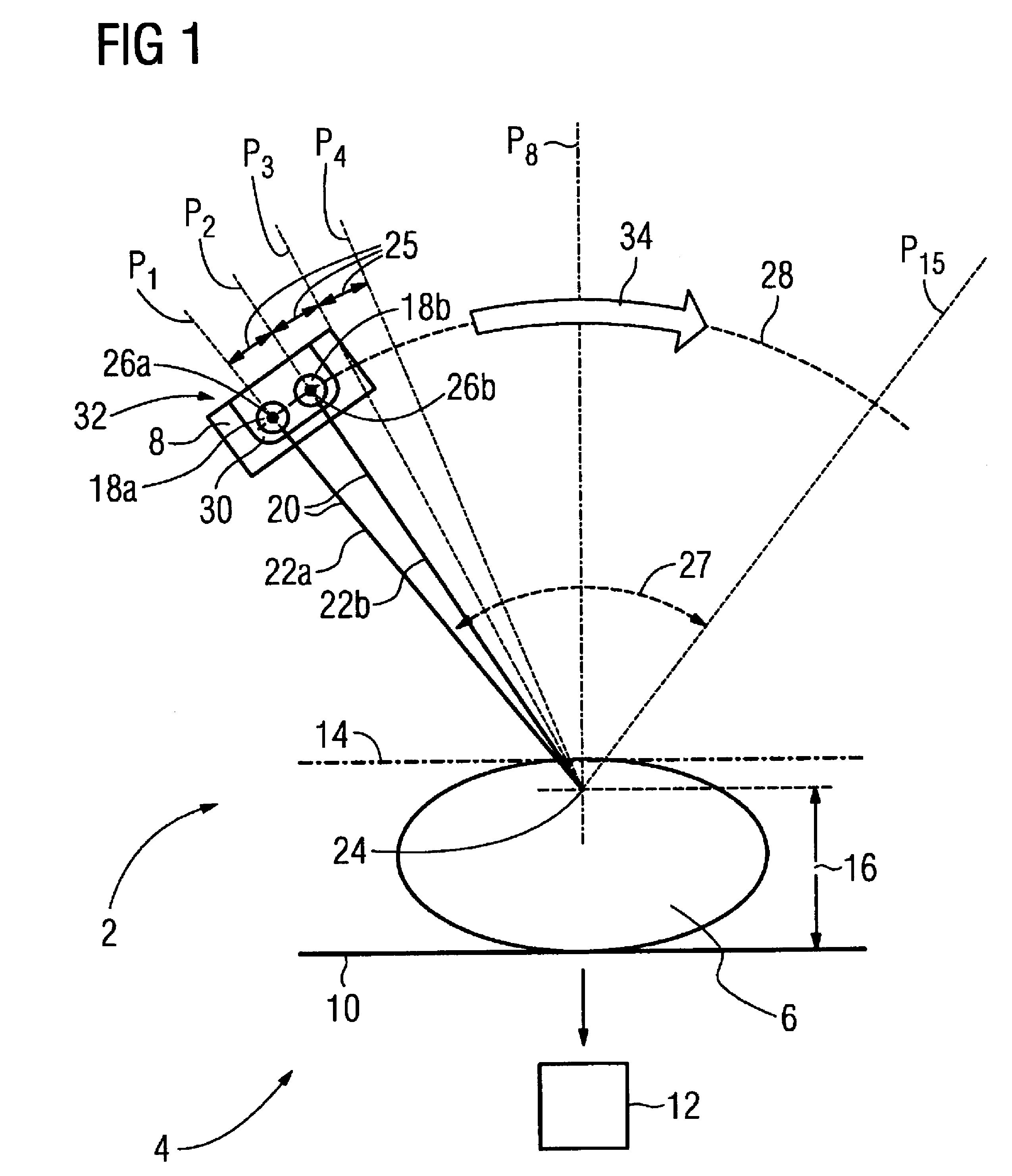
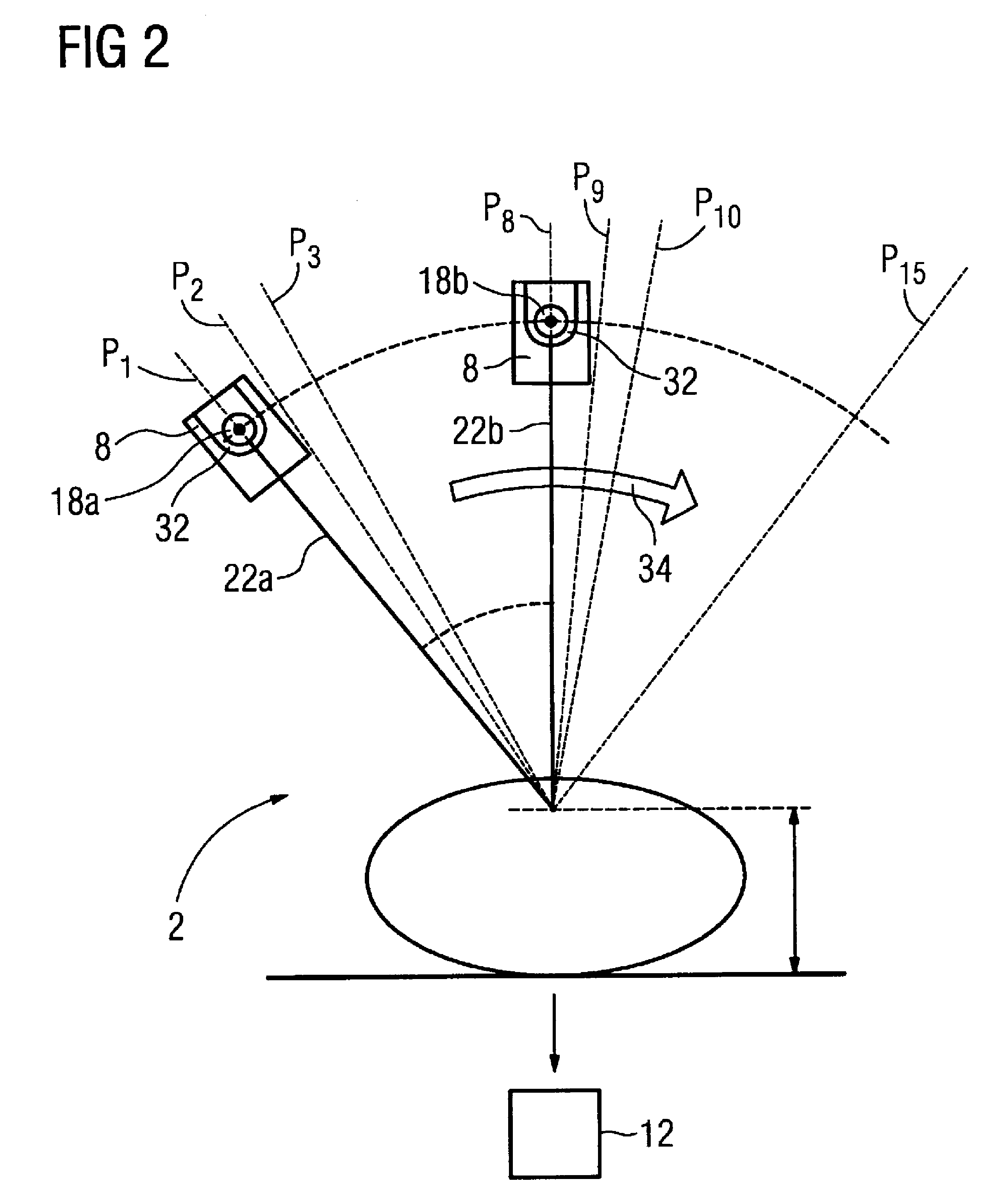
[0028]FIG. 1 shows an x-ray system 2 for tomosynthetic scanning of a female breast 6 fixed in a retention device 4. The x-ray system 2 comprises an x-ray source 8 and a 2D flat panel detector 10 to acquire 2D x-ray images 12. The flat panel detector 10 moreover serves as a first compression plate of the retention device 4 which comprises a second compression plate 14, between which flat panel detector 10 and compression plate 14 the breast 6 is compressed in the direction of the double arrow 16.

[0029]The x-ray source 8 comprises two radiation sources 18a,b which respectively emit x-ray radiation 20 in the direction of a center beam axis 22a,b. The center beam axes 22a,b intersect at a point of a pivot axis 24 runs perpendicular to the plane of the drawing in FIG. 1, and therefore inside the breast 6, parallel to the flat panel detector 10 or, respectively, the compression plate 14.

[0030]The entire x-ray source 8 can also be panned on this pivot axis 24 so that respective focus point...


PUM

PropertyMeasurementUnit
angleaaaaaaaaaa
focal diameteraaaaaaaaaa

Abstract

In an x-ray system and a method for tomosynthetic scanning of a subject, x-ray radiation is emitted from two x-ray sources that are panned along a line relative to the subject during a tomosynthetic scan. The two x-ray sources are located next to each other along the line, and each emit an x-ray beam. X-rays from the two parallel beams attenuated by the subject are detected by a two-dimensional x-ray detector, that is substantially stationary during the tomosynthetic scan.

Description

BACKGROUND OF THE INVENTION[0001]1. Field of the Invention[0002]The invention concerns an x-ray system and a method for tomosynthetic scanning of a subject.[0003]2. Description of the Prior Art[0004]3D imaging methods increasingly assert themselves in medical technology. For example, computed tomography (CT), in which an x-ray tube and its opposite detector orbit a patient as an examination subject in order to generate slice exposures of the patient, is hereby a complicated and expensive method. An entire 3D volume is subsequently reconstructed from the slice exposures.[0005]A distinctly less complicated 3D imaging method is digital tomosynthesis, which is in particular developed in connection with mammography. In contrast to CT, an x-ray source is hereby panned around an examination subject as a center of the movement only within a limited angle range, for example ±20° starting from a middle position. An x-ray detector to receive the x-rays hereby remains essentially stationary, i....

Claims


Application Information

Patent Timeline
Patent Type & Authority Patents(United States)
IPC IPC(8): G01N23/04
CPCA61B6/025A61B6/032A61B6/4007A61B6/4028A61B6/482G01N23/046A61B6/4241G01N2223/419G01N2223/1016G01N2223/206G01N2223/414G01N2223/612H01J2235/08
Inventor MERTELMEIER, THOMAS
Owner SIEMENS HEALTHCARE GMBH
Why Eureka
Try Eureka