System for the delivery of proton therapy

a proton therapy and proton beam technology, applied in the field of proton therapy delivery systems, can solve the problems of not being able to build such a gantry 1 system at psi, scan too slow for repeatedly applying target repainting, etc., and achieve the effect of reducing the range of magnetic scanning—on and avoiding the broadening of the beam due to mcs

Inactive Publication Date: 2009-07-14
PAUL SCHERRER INSTITUT
View PDF9 Cites 82 Cited by
  • Summary
  • Abstract
  • Description
  • Claims
  • Application Information

AI Technical Summary

Benefits of technology

[0034]The use of a reduced range of magnetic scanning—on a small compact nozzle and a small air gap to the patient allow to design a very compact gantry which brings an almost unscattered (due to the short distance) proton beam into the target volume. The use of the two-dimensional parallelism of scanning—for the field size extension using the patient table on the basis of a “geometrical” field patching—which opens up the option to use a slow continuous table motion during multiple target rescannings in order to compensate the comparably small cross-sectional scanning area at the nozzle.
[0035]The possibility, by virtue of the design of the beam optics, to scan the beam in two dimensions while keeping the direction and the shape of the beam unchanged (parallel beam scanning) is a major characteristics of the PSI Gantry 2. Strong emphasis is given on the utilization of this important feature. The parallelism of scanning can be used for extending the range of beam scanning beyond the given magnetic scanning range, by combining it with the patient table motion in a simple procedure, which is independent of treatment planning (“geometrical” field patching). While using a geometrical field patching technique the patient table can be moved very slowly and continuously, by compensating the displacement of the table motion with an offset applied to the sweepers (field patching applied with continuous table motion). This approach is very attractive especially in the context of multiple target repaintings, which are needed in the presence of organ motion (slow table motion during multiple target repaintings). The geometric field patching method allows overcoming the problems posed by a limited range of magnetic scanning. This feature can then be used for designing a nozzle which is small in size in both transverse directions to the beam (slim very compact nozzle) as given by the defined size of the cross-sectional scanning area. The use of a slim nozzle is the preferred solution for placing the patient very close to a pre-absorber system and to the beam monitors, both enclosed in the nozzle (small air gap to the patient), without colliding with patient shoulders, to avoid the broadening of the beam due MCS in the air gap to the patient.
[0040]Therefore, it is now possible to perform the magnetic scan (at each iso-energy layer) along the target contour (at that proton depth) and on similar equidistant contours in the interior of the target (contoured double magnetic scanning). The concentric contours are scanned with close-to-maximum speed by shaping the dose using the beam intensity modulation controlled at the ion source of the accelerator. By this method scanning speed is gained and thus a large amount of target repaintings can be applied. Additionally, the best possible quality of the lateral fall-off of the dose distribution at the edge of the field can be obtained and the dynamics for the beam intensity variations can be kept low, while working with maximum speed of scanning. By virtue of the 1:1 imaging of the beam optics of Gantry 2 from the coupling point of the gantry to the isocenter, an imaged (virtual) collimation on the scanned beam spots can be applied by using a (real) collimator block (moving radially and azimuthally) at the coupling point of the gantry (contoured double magnetic scanning with imaged collimation applied to a scanned broad beams).

Problems solved by technology

Without pushing the compactness of the system down to only 4 m diameter it would not have been possible to build such a Gantry 1 system at PSI.
The eccentric mounting of the patient is now the most often criticized point, since the patient table moves away from the floor and the patient couch is not accessible to the personnel when the proton beam is applied from below.
The use of two mechanical systems makes the scan too slow for applying repeatedly target repainting.

Method used


Image

  • System for the delivery of proton therapy
  • System for the delivery of proton therapy
  • System for the delivery of proton therapy

Examples


Embodiment Construction

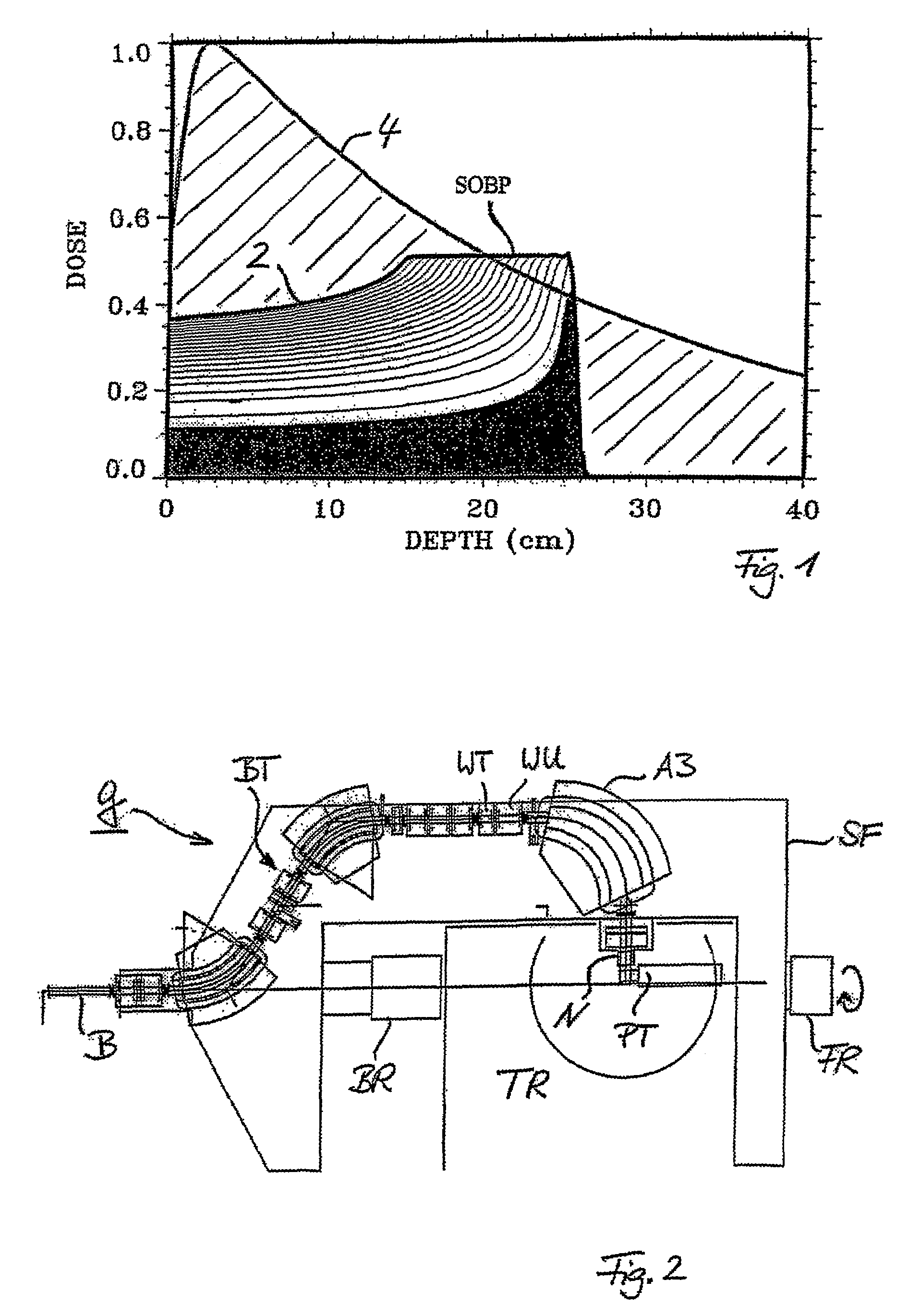
[0053]FIG. 1 shows a schematic diagram of the depth dose distribution of protons (graph 2) in comparison to the depth dose distribution of photons (graph 4) in human tissue equivalent material. The advantage of proton therapy is given by its superior physical selectivity, which allows to design a plateau SOBP (the so-called spread out Bragg peak) for the dose in a distinct depth of the target volume which is located within the patient. Protons have a well-defined penetration range in biological tissue and they deposit the maximum of their energy in the region where they stop. This gives rise to the so-called Bragg peak, which is shown in FIG. 1 as the dose deposition of a mono-energetic proton beam as a function of depth. This must be compared with clinical photons, which have a characteristic exponential fall-off of the dose (graph 4).

[0054]Due to their electric charge protons offer the possibility to localize the dose not only in the lateral directions by the magnetic scanning tec...


PUM


Abstract

A process for an intensity-modulated proton therapy of a predetermined volume within an object includes discretising the predetermined volume into a number of iso-energy layers each corresponding to a determined energy of the proton beam. A final target dose distribution is determined for each iso-energy layer. The final target dose distribution or at least a predetermined part of this final target dose distribution is applied by parallel beam scanning by controlling the respective beam sweepers, thereby scanning one iso-energy layer after the other using an intensity-modulated proton beam while scanning a predetermined iso-energy layer.

Description

BACKGROUND OF THE INVENTION[0001]The invention relates to a system and a method for applying an intensity-modulated proton therapy on a predetermined tumor volume within the body of the patient.[0002]The number of new hospital-based facilities for charged particles therapy is growing quickly, especially in Japan and in the USA. Proton therapy is becoming a realistic therapeutic possibility for treating well-selected cancer types in centralized large hospitals.[0003]All new commercial systems are based on the passive scattering technique. The compact gantry for proton therapy at the Swiss Paul Scherrer Institute (PSI) is still the only facility in the world using a dynamic beam delivery technique based on the active scanning of a small proton pencil beam. Only at the German GSI facility (GSI=Gesellschaft fur Schwerionenforschung, Darmstadt) is a similar beam delivery technique used, with carbon ions in a horizontal beam line. By using this modern approach to radiation therapy the con...

Claims


Application Information

Patent Timeline
Patent Type & Authority Patents(United States)
IPC IPC(8): H01J3/32G21G1/10A61N5/10G21K1/093G21K5/04H05H7/00
CPCA61N5/10A61N5/1043H05H7/00G21K1/093G21K5/04A61N2005/1087A61N2005/1095
Inventor PEDRONI, EROS
Owner PAUL SCHERRER INSTITUT
Why Eureka
Try Eureka