Foot peg with replaceable cleat component

a technology of foot pegs and cleats, applied in the field of foot pegs, can solve the problems of debris falling through, and achieve the effect of inhibiting the buildup of debris

Active Publication Date: 2011-05-24
TURN 14 DISTRIBUTION INC
View PDF18 Cites 5 Cited by
  • Summary
  • Abstract
  • Description
  • Claims
  • Application Information

AI Technical Summary

Benefits of technology

[0004]The present invention presents the rare opportunity to create an entirely new foot peg for use in power sport vehicles that does not suffer from the disadvantages, limitations, and problems mentioned above. From the foregoing it may be appreciated that a need has arisen for an improved foot peg in which the cleated surface may be replaced without replacing the entire foot peg thereby allowing for economical and quick replacement of worn cleats and for replacement of cleats with different types of cleats in order to adjust the height and / or grip of the foot peg to suit the requirements and / or preferences of the rider and / or conditions of the riding surface.
[0005]According to one aspect of the invention, a foot peg for use on motor sport vehicles such as motorcycles and ATVs is provided that includes a base component and a cleat component. The base component has a first base member, a second base member, and a third base member, wherein the first base member is configured to attach the base component to the vehicle, the second and third base members extend from the first base member away from the vehicle, and the second and third base members extend away from each other such that the second and third base members define a space between at least a part of the second and third base members sufficiently large to allow debris to fall there through. The cleat component includes a plurality of cleats to provide a grippable surface upon which a rider may place a foot and an attaching member for attaching the cleat component to the base component. The plurality of cleats are arranged such that at least one opening is defined between the plurality of cleats. The opening is sufficiently large such that debris may fall there through. At least a portion of the opening aligns with the space between the second and third base members such that debris falling through the opening may also fall through the space. The cleat component may be replaced without removal of the base component from the vehicle.
[0007]According to yet another aspect of the present invention, a foot peg is provided that includes a base component comprising means for attaching the foot peg to a power sport vehicle, such as, for example, a motorcycle or ATV, and a detachable cleat component. The base component defines an opening and the detachable cleat component comprises a plurality of cleats defining at least one hole therethrough. The hole and the opening in the base component align sufficiently to allow debris to fall from an upper surface of the cleat component through the foot peg so as to inhibit build up of debris on the upper surface of the cleat component. The foot peg also includes means for attaching the detachable cleat component to the base component.
[0008]According to yet another aspect of the present invention, a foot peg is provided that includes a base component and a removable cleat component. The base component includes a vehicle attachment component and comprises a shape defining at least one first opening sufficient in size for debris to fall therethrough. The removable cleat component comprises a plurality of cleats arranged such that at least one second opening of sufficient size for debris to fall through is defined therebetween. The removable cleat component is mechanically attached to the base component and the removable cleat component is configured such that the removable cleat component may be replaced without removal of the base component from the frame of a power sport vehicle.

Problems solved by technology

The opening is sufficiently large such that debris may fall there through.

Method used


Image

  • Foot peg with replaceable cleat component
  • Foot peg with replaceable cleat component
  • Foot peg with replaceable cleat component

Examples


Embodiment Construction

[0025]It should be understood at the outset that although an exemplary implementation of the present invention is illustrated below, the present invention may be implemented using any number of techniques, whether currently known or in existence. The present invention should in no way be limited to the exemplary implementations, drawings, and techniques illustrated below, including the exemplary design and implementation illustrated and described herein. Additionally, the drawings contained herein are not necessarily drawn to scale. Like reference numerals refer to like and similar components throughout the application.

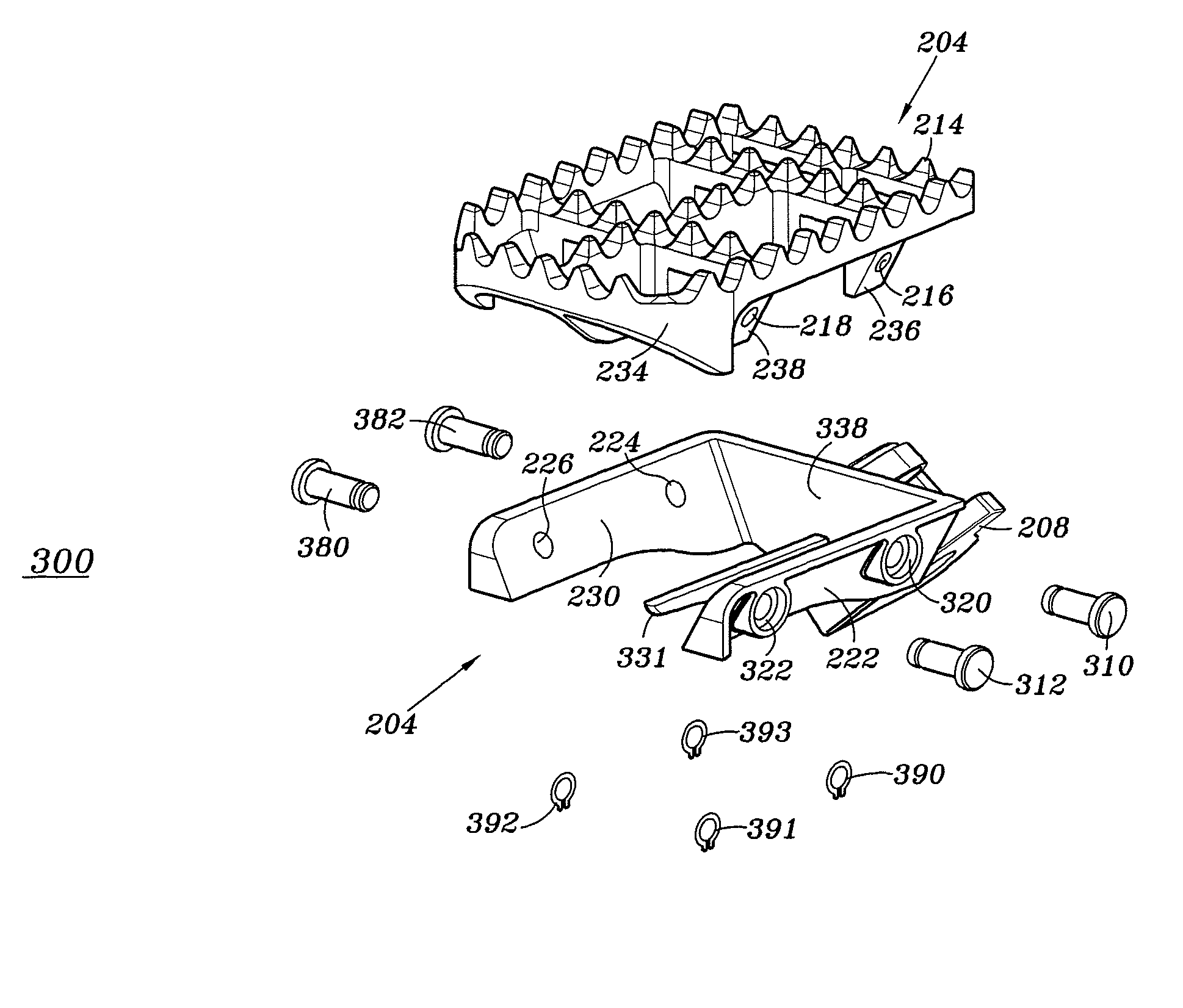
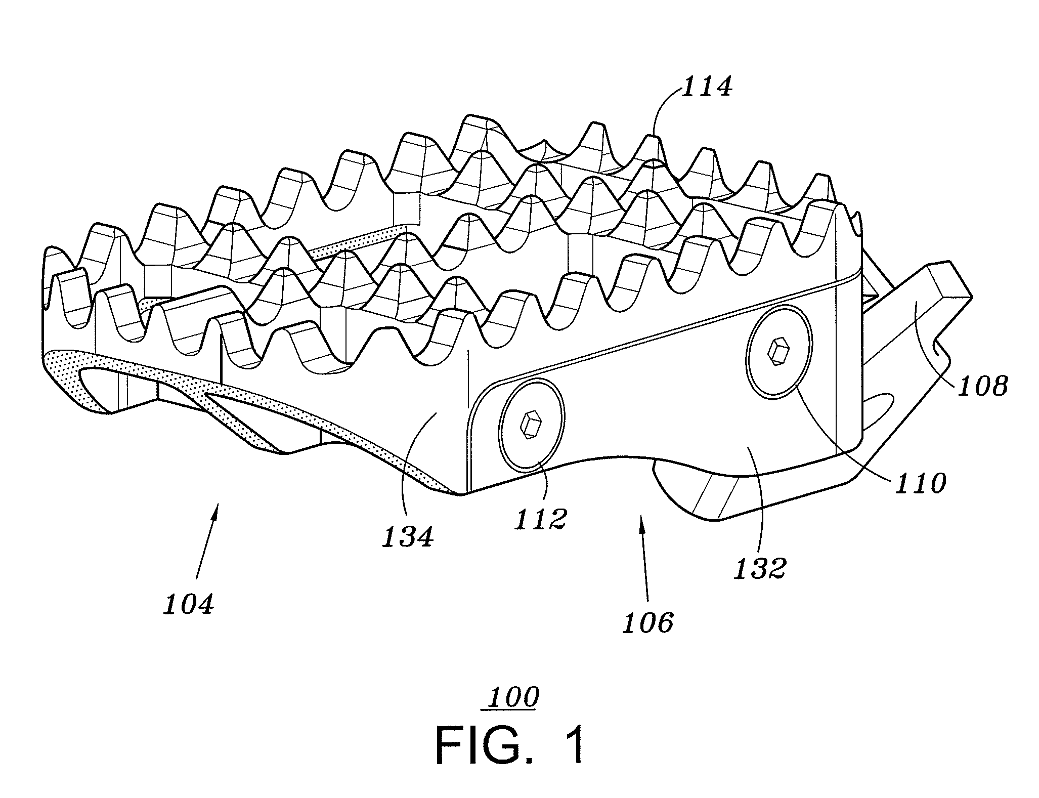
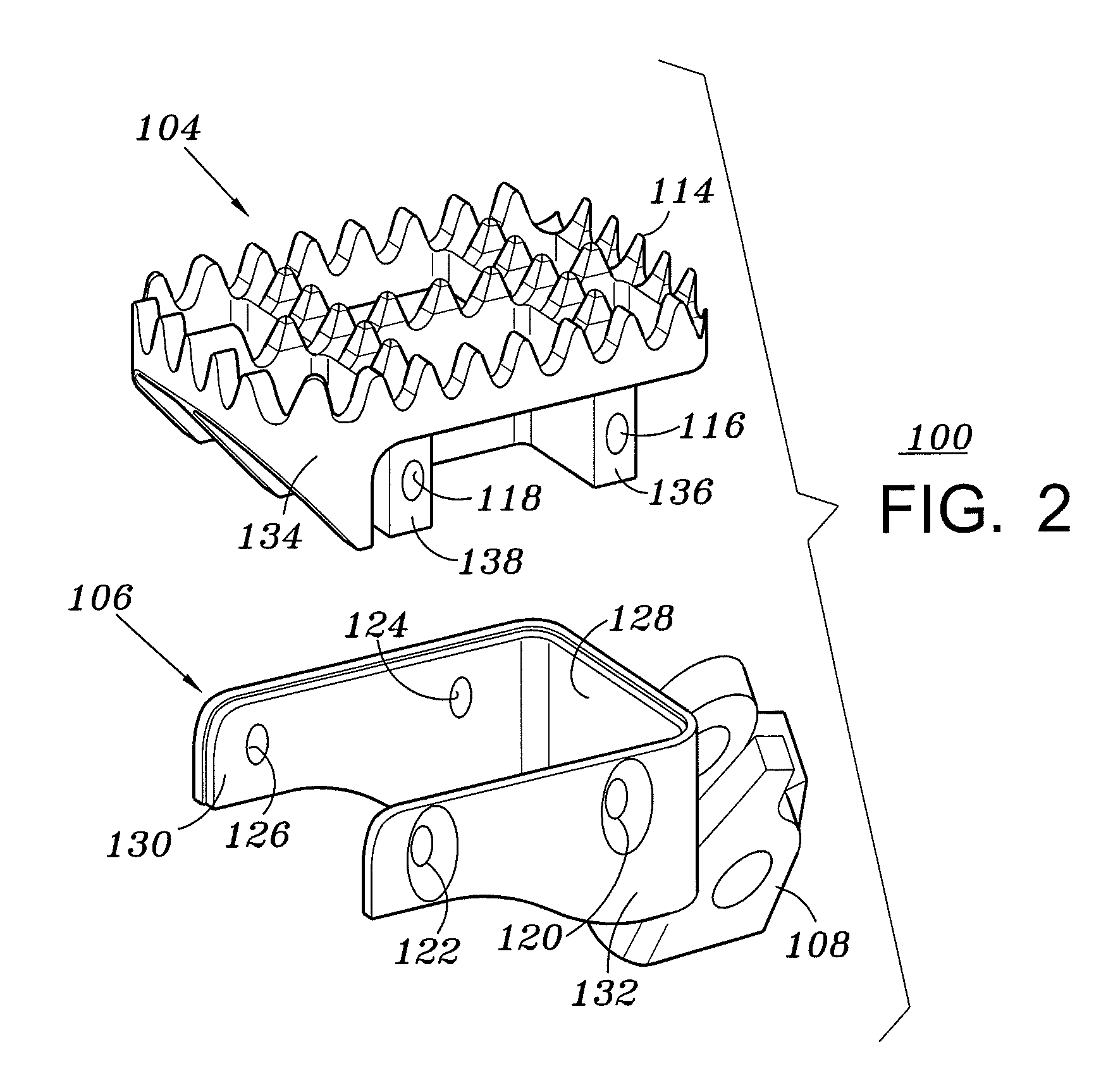
[0026]With reference now to the figures, and in particular with reference to FIGS. 1-7. FIG. 1 is a perspective view of an exemplary multi-piece foot peg 100 having a base and removable cleat component in accordance with one embodiment of the present invention. FIG. 2 is an exploded perspective view of foot peg 100 in accordance with one embodiment of the present inve...


PUM


Abstract

An multi-piece foot peg for use with power sport vehicles such as motorcycles and ATVs is provided that, in one embodiment, includes a base that attaches to the frame of the vehicle and a cleat member that attaches to the base wherein the cleat member may be replaced without replacing the entire foot peg thereby enabling economical replacement of worn cleats and enabling the adjustment of foot peg height and aggressiveness of the cleats. The base is configured to define an opening between two sub-components that extend away from the frame of the vehicle. The cleat member includes cleats and at least one opening between the cleats positioned to facilitate the passage of debris through the opening in the cleat member and through the opening in the base such that debris will not build up on the upper surface of the cleat member.

Description

TECHNICAL FIELD OF THE INVENTION[0001]This invention relates in general to the field of vehicles and, more particularly to foot pegs for use on motorcycles, all terrain vehicles, and similar vehicles.BACKGROUND OF THE INVENTION[0002]Motocross motorcycles and many other similar vehicles, such as, for example, small motorized three and four wheel vehicles commonly referred to as All Terrain Vehicles (ATVs), have foot pegs that extend out from the body of the vehicle that allow a rider to stand and support himself when riding. These foot pegs typically contain a cleated surface that provide the rider with greater grip and traction than would otherwise be available thereby helping to prevent the rider's foot from inadvertently slipping off of the foot peg.[0003]As the cleated surface of the foot pegs wear down over time, the traction provided to the rider is lessened. Therefore, it is common that the foot peg must be replaced with a new one in order to provide the rider with a foot peg ...

Claims


Application Information

Patent Timeline
Patent Type & Authority Patents(United States)
IPC IPC(8): G05G1/60B62M3/00B62J25/00B60N3/06
CPCB62J25/00G05G1/483G05G1/60Y10T74/2168Y10T74/20918B62J25/06
Inventor SMITH, BRAD
Owner TURN 14 DISTRIBUTION INC
Why Eureka
Try Eureka