
Vehicle control apparatus and method

a technology of vehicle control and control apparatus, which is applied in electrical control, machine/engine, separation process, etc., can solve the problems of deteriorating the function of such a catalyst for exhaust gas purification, reducing the temperature of exhaust gas, and reducing the efficiency of catalyst function, so as to improve fuel economy and recover the effect of catalyst function

Inactive Publication Date: 2011-05-24
TOYOTA JIDOSHA KK
View PDF11 Cites 1 Cited by
  • Summary
  • Abstract
  • Description
  • Claims
  • Application Information

AI Technical Summary

Benefits of technology

[0010]The invention provides a vehicle control apparatus and a vehicle control method that achieve both the improvement of the fuel economy and the recovery of the catalyst function effectively.
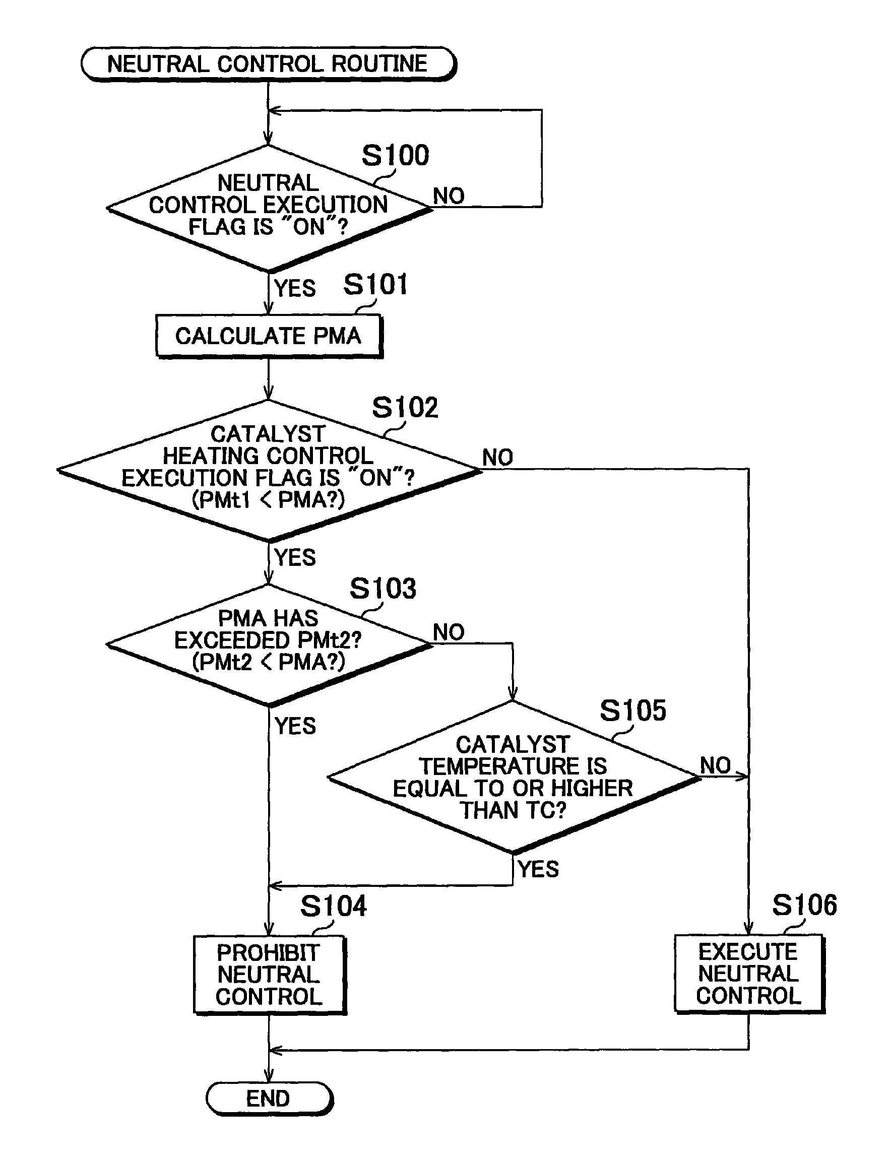
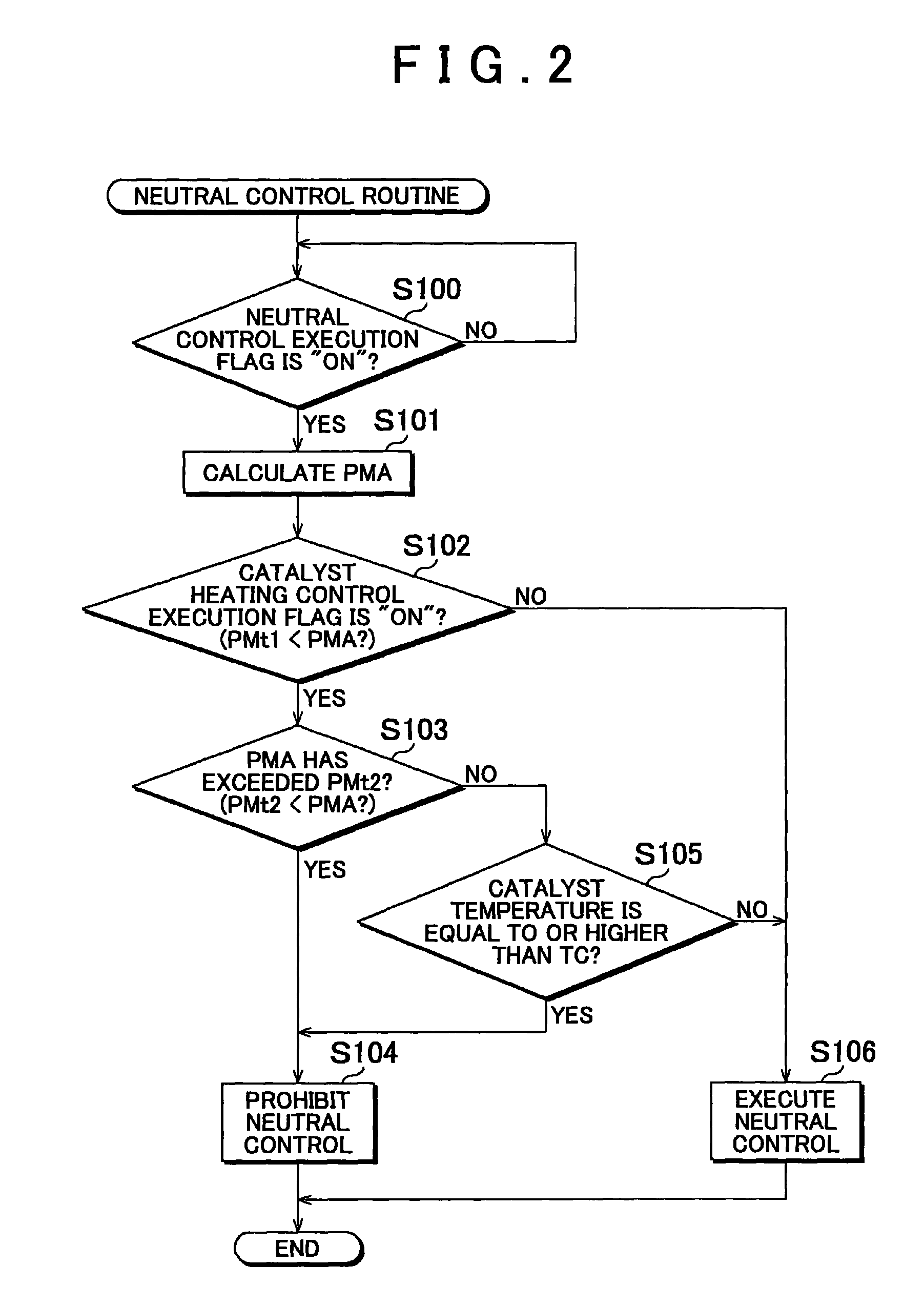
[0012]According to the vehicle control apparatus and a vehicle control method described above, when the amount of exhaust matter accumulated in the catalyst has exceeded the second reference value, that is when the function of the catalyst has largely deteriorated and the necessity of executing the catalyst heating control is high, the execution of the neutral control is prohibited. This feature helps recover the function of the catalyst although the fuel economy improving effect by the neutral control lessens. On the other hand, when the amount of exhaust matter accumulated in the catalyst is equal to or smaller than the second reference value, that is when the necessity of executing the catalyst heating control is low, the neutral control is executed and therefore the fuel economy improves accordingly. According to the vehicle control apparatus and a vehicle control method descried above, as such the execution of the neutral control is prohibited in accordance with the degree of deterioration of the function of the catalyst during the catalyst heating control, so that the improvement of the fuel economy and the recovery of the catalyst function are both achieved effectively.

Problems solved by technology

Normally, the function of such an exhaust gas purification catalyst deteriorates as the amount of the particulate matter accumulated in the exhaust gas purification catalyst increases.
However, because the load of the internal combustion engine decreases during the neutral control, if the duration of the neutral control is excessively long, it leads to a decrease in the exhaust gas temperature.
As such, in vehicles in which the neutral control and the aforementioned catalyst heating control are both executed, if the neutral control is executed during the catalyst heating control, it may cause a decrease in the exhaust gas temperature and thus may make it difficult for the accumulated particulate matter to be combusted and thus removed, resulting in a delay in recovering the function of the exhaust gas purification catalyst.
Further, executing the neutral control unavoidably causes a delay in recovering the function of the exhaust gas purification catalyst although contributing to improving the fuel economy.
Such problems occur not only to vehicle control apparatuses adapted to execute a control for increasing the temperature of a catalyst to combust and thus remove particulate matter in the catalyst, but also to vehicle control apparatuses that execute a catalyst heating control for various other purposes, such as those adapted to execute a control for increasing the temperature of a catalyst to remove sulfur in the catalyst.

Method used


Image

  • Vehicle control apparatus and method
  • Vehicle control apparatus and method
  • Vehicle control apparatus and method

Examples


Embodiment Construction

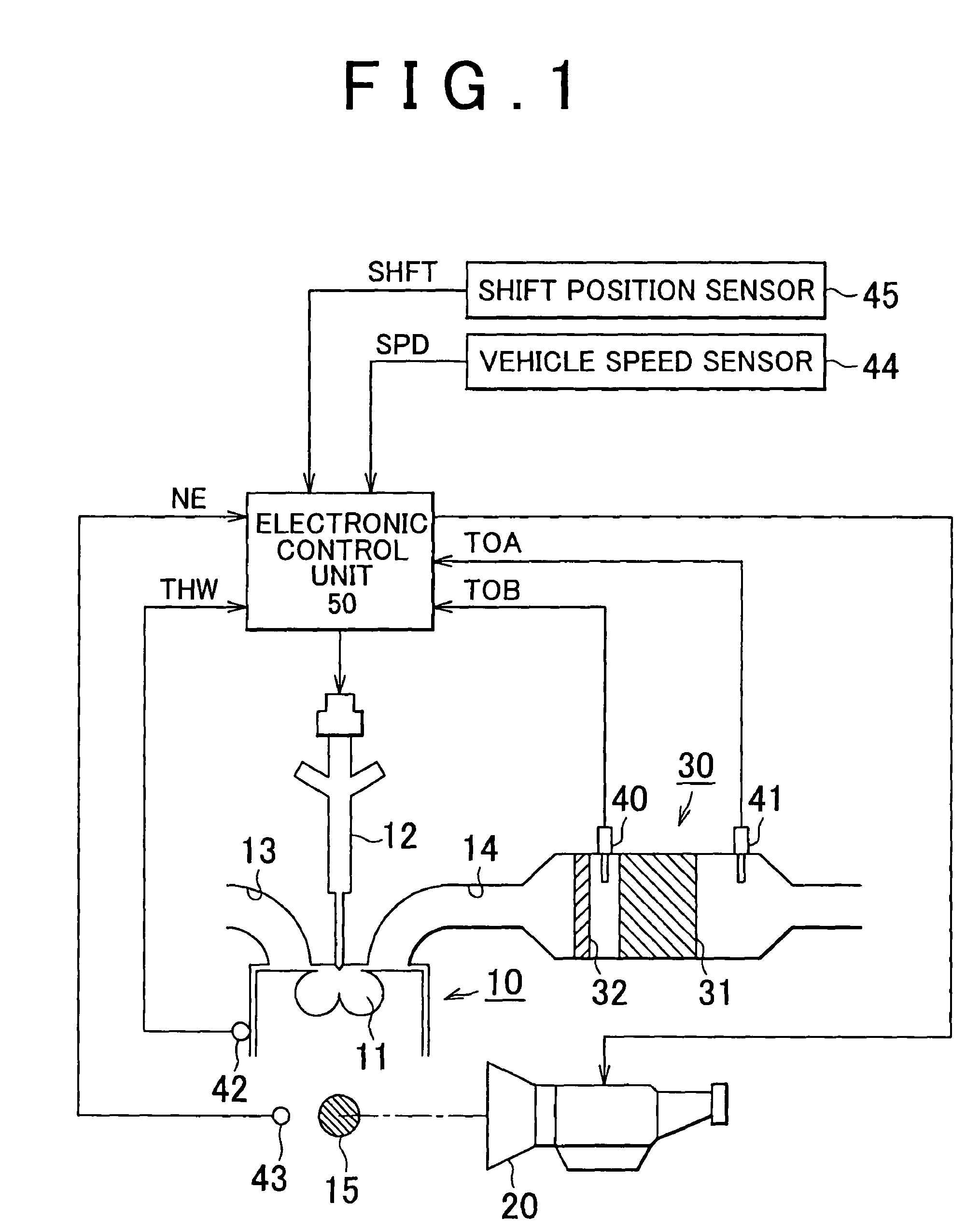
[0016]Hereinafter, a vehicle control apparatus according to an example embodiment of the invention will be described with reference to FIG. 1 and FIG. 2.

[0017]First, the overall configuration of the vehicle control apparatus of this example embodiment will be described with reference to FIG. 1. Referring to FIG. 1, in an engine 10 of the vehicle, air-fuel mixtures formed of the fuel injected from fuel injection valves 12 and the intake air supplied from an intake passage 13 are combusted in combustion chambers 11, and the exhaust gas produced from the combustion is discharged to an exhaust passage 14. The engine 10 has a crankshaft 15 that is the output shaft of the engine 10. The crankshaft 15 is rotated by the energy produced from the combustion in each combustion chamber 11. The engine 10 is connected to an automatic transmission 20 via the crankshaft 15. The automatic transmission 20 changes the output torque of the engine 10. More specifically, the automatic transmission 20 cha...


PUM


Abstract

A vehicle control apparatus includes a controller. When predetermined conditions are satisfied, the controller executes a neutral control that forcibly places an automatic transmission in a substantially neutral state, the predetermined conditions including the shift position of the automatic transmission being in the drive position. When it is determined that the amount of exhaust matter accumulated in a catalyst provided in an exhaust system of a vehicle has exceeded a first reference value, the controller executes a catalyst heating control that increases the temperature of the catalyst so as to remove the exhaust matter accumulated in the catalyst. When it is determined during the catalyst heating control that the amount of the exhaust matter accumulated in the catalyst has exceeded a second reference value that is larger than the first reference value, the controller prohibits the execution of the neutral control.

Description

INCORPORATION BY REFERENCE[0001]The disclosure of Japanese Patent Application No. 2006-352581 filed on Dec. 27, 2006 including the specification, drawings and abstract is incorporated herein by reference in its entirety.BACKGROUND OF THE INVENTION[0002]1. Field of the Invention[0003]The invention relates to a vehicle control apparatus and method that executes a neutral control that forcibly places an automatic transmission of a vehicle in a substantially neutral state when the shift position of the automatic transmission is in the drive position and a catalyst heating control that increases the temperature of a catalyst provided in the exhaust system.[0004]2. Description of the Related Art[0005]An exhaust gas purification device for internal combustion engines, such as vehicle diesel engines, reduces the particulate matter (PM: Particulate Matter) discharged outside of the internal combustion engine by trapping the particulate matter contained in the exhaust gas discharged from the ...

Claims


Application Information

Patent Timeline
Patent Type & Authority Patents(United States)
IPC IPC(8): F16H59/50B60W10/10B01D53/94B60W30/18F01N3/023F01N3/20F01N3/24F16H59/78F16H61/20
CPCB60W30/18054F02D41/0225F02D41/023F02D41/029Y10T477/65B60W2510/0638B60W2510/068F01N3/023F01N3/035F02D2200/0802F02D2200/0812F02D2200/502F16H61/16Y10T477/663F16H2061/168B60Y2300/476Y10T477/653B60W2510/0623
Inventor KOBAYASHI, MASAAKI
Owner TOYOTA JIDOSHA KK
Learn More