Electronic device

a technology of electronic devices and cameras, applied in the direction of instruments, portable computer details, electric apparatus casings/cabinets/drawers, etc., can solve the problems of difficult to dispose of cameras near the locking mechanism and unfavorable placemen

Inactive Publication Date: 2011-05-24
FUJITSU CLIENT COMPUTING LTD
View PDF26 Cites 31 Cited by
  • Summary
  • Abstract
  • Description
  • Claims
  • Application Information

AI Technical Summary

Benefits of technology

[0027]A board for a camera is usually mounted with a heat-generating component for signal processing. In that case, if the surface of the linking mechanism overlapping with the board is covered with a metal sheet, it is possible to disperse heat from the heat-generating component. In addition, the metal sheet is capable of serving as an electromagnetic shield and thus suppressing malfunction of the signal processing circuit.
[0029]If the bent metal sheet is used, strength of the linking mechanism and its neighborhood is increased, which makes the electronic device thinner than a resin part having the same degree of strength.

Problems solved by technology

Thus, it is difficult to dispose the camera near the locking mechanism.
Accordingly, when both the camera and the locking mechanism are installed in the note PC, either of the camera and the locking mechanism, due to insufficient space, should be placed close to the right or left side off the center of the top edge of the display unit, which is not favorable placement.
Further, this problem is not limited to the note PC and is common to an electronic device with two cabinets that are configured to be opened and closed with respect to each other such as a PDA and a DVD.

Method used


Image

  • Electronic device
  • Electronic device
  • Electronic device

Examples


Embodiment Construction

[0072]An embodiment of the present invention will be described below. The following description will be given of a notebook PC, which is an example of the electronic device of the present invention.

(General Configuration)

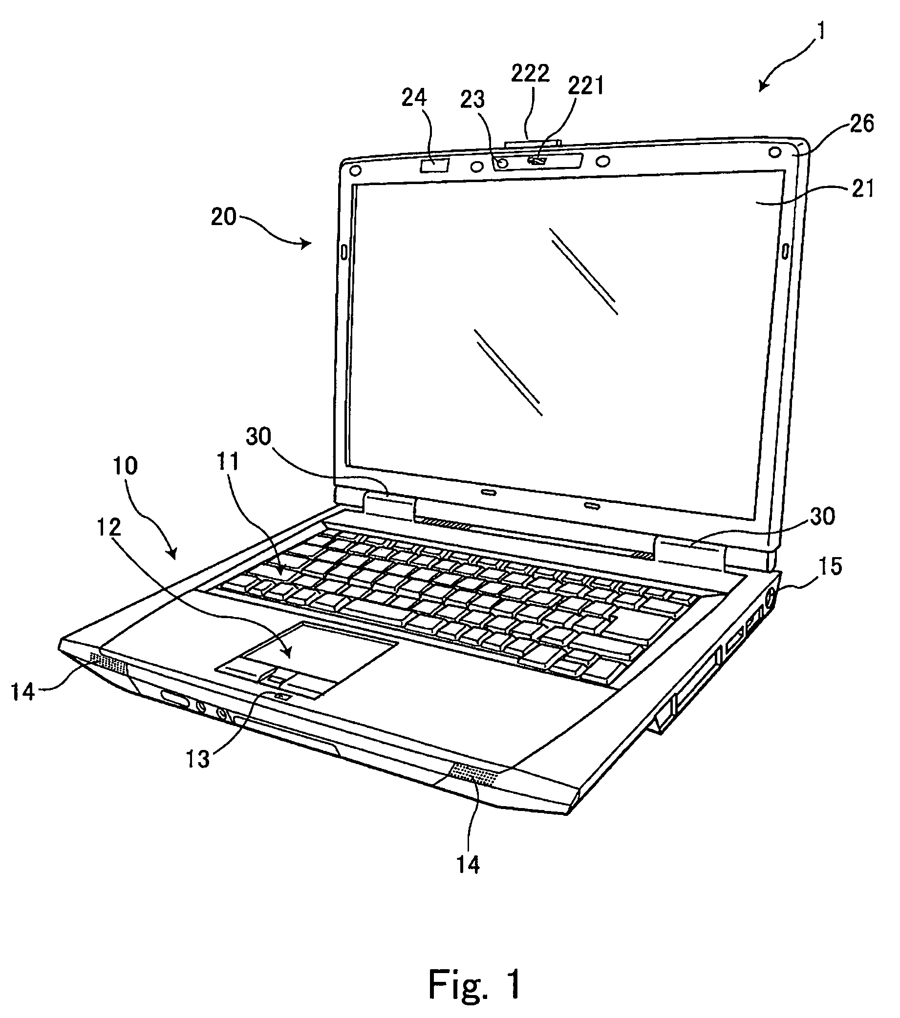
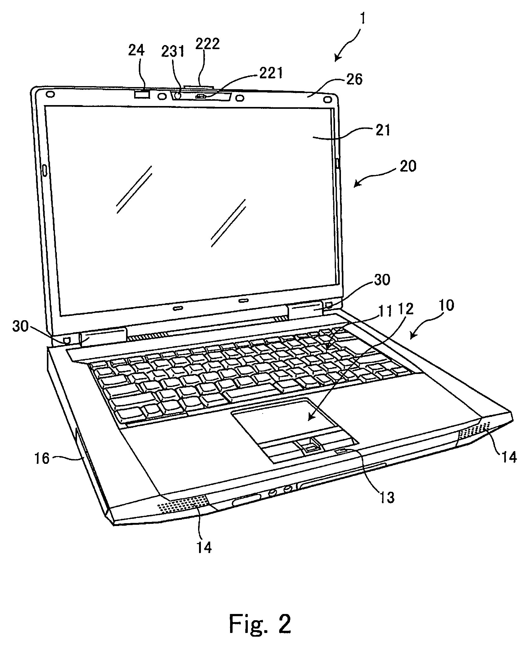
[0073]FIGS. 1 and 2 are perspective views of the appearance of a notebook PC, showing an open condition as viewed from different directions. FIG. 3 is a perspective view showing the notebook PC in a closed condition. And FIG. 4 is a perspective view showing the bottom surface side of the notebook PC in a closed condition.

[0074]This notebook PC 1 is composed of a main unit 10 and a display unit 20, and the display unit 20 is connected so as to be able to open and close between a closed condition in which the display unit 20 is superposed on the main unit 10 (see FIG. 3) and an open condition in which the display unit 20 is opened from the main unit 10 by a hinge portion 30 (see FIGS. 1 and 2).

[0075]The main unit 10 is provided, on the top surface thereof, with a keyb...


PUM


Abstract

An electronic device has a first cabinet and a second cabinet. The second cabinet has a locking module including a hook, an operation member and a linking mechanism. The hook is formed at a position near a top end of the second cabinet around the center in the lateral direction in opened state, and is engaged with the first cabinet to lock the second cabinet in the closed state. The operation member disengages the hook from the first cabinet in response to operation. The linking mechanism links the operation to movement of disengaging the hook. The second cabinet further has a board mounted with a camera module having an image taking lens and an imaging device and a signal processing circuit for the camera module. The board is disposed at such a position that a portion in which the signal processing circuit is mounted overlaps with the linking mechanism.

Description

BACKGROUND OF THE INVENTION[0001]1. Field of the Invention[0002]The present invention relates to an electronic device having a first cabinet and a second cabinet that is supported via a pivot of the first cabinet so as to be opened and closed.[0003]2. Description of the Related Art[0004]A notebook personal computer (hereafter referred to as note PC) is formed by a main unit (a first cabinet) provided with a keyboard on a top surface thereof and a display unit (a second cabinet) provided with a display screen that can be opened and closed with respect to the main unit. Recently, such a note PC equipped with a camera at a position near the top edge of the display unit has started to become popular. The camera is intended for photographing a user's face and using the photographed image for communication via TV, telephone and the like.[0005]Further, a note PC is usually provided with locking mechanism that prevents the closed note PC from being unintentionally opened when the display un...

Claims


Application Information

Patent Timeline
Patent Type & Authority Patents(United States)
IPC IPC(8): G06F1/16
CPCG06F1/1616G06F1/1637G06F1/1688G06F1/1681G06F1/1658
Inventor TATSUKAMI, IKKIWATANABE, HIDEKI
Owner FUJITSU CLIENT COMPUTING LTD
Why Eureka
Try Eureka