
Turbine engine compressor

a compressor and turbine engine technology, applied in combination engines, machines/engines, gearing details, etc., can solve the problems fan speed, and achieve the effect of low spool speed

Inactive Publication Date: 2011-05-31
RTX CORP
View PDF15 Cites 43 Cited by
  • Summary
  • Abstract
  • Description
  • Claims
  • Application Information

AI Technical Summary

Benefits of technology

This configuration enables a more compact and lightweight engine design with increased pressure ratio and thrust, while maintaining aerodynamic efficiency and reducing part count, by allowing the low spool to drive the fan efficiently through a reduction gearing system.

Problems solved by technology

In designing an engine, there may be a mismatch between desirable fan speed and desirable low spool speed.

Method used


Image

  • Turbine engine compressor
  • Turbine engine compressor
  • Turbine engine compressor

Examples


Embodiment Construction

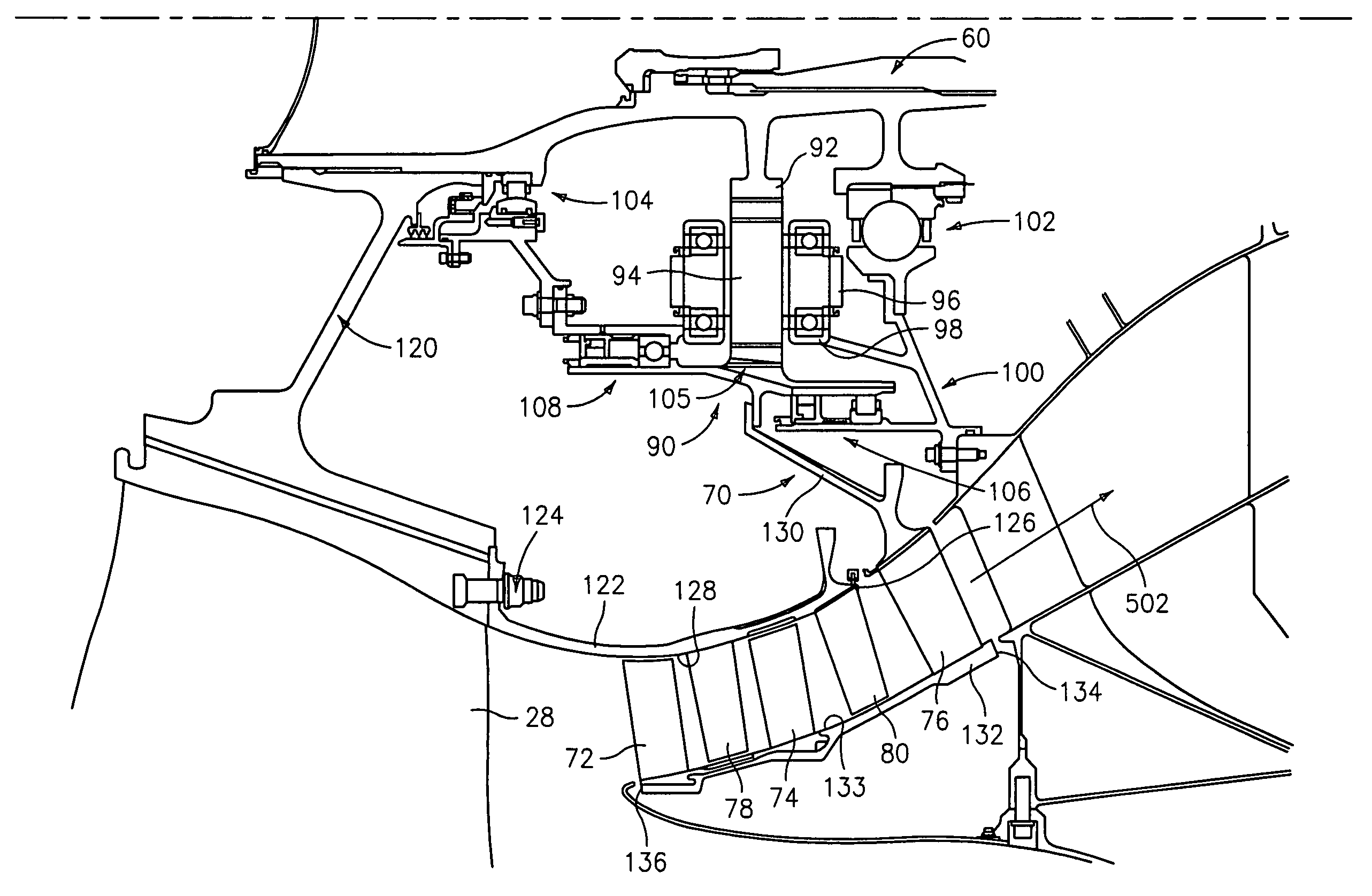
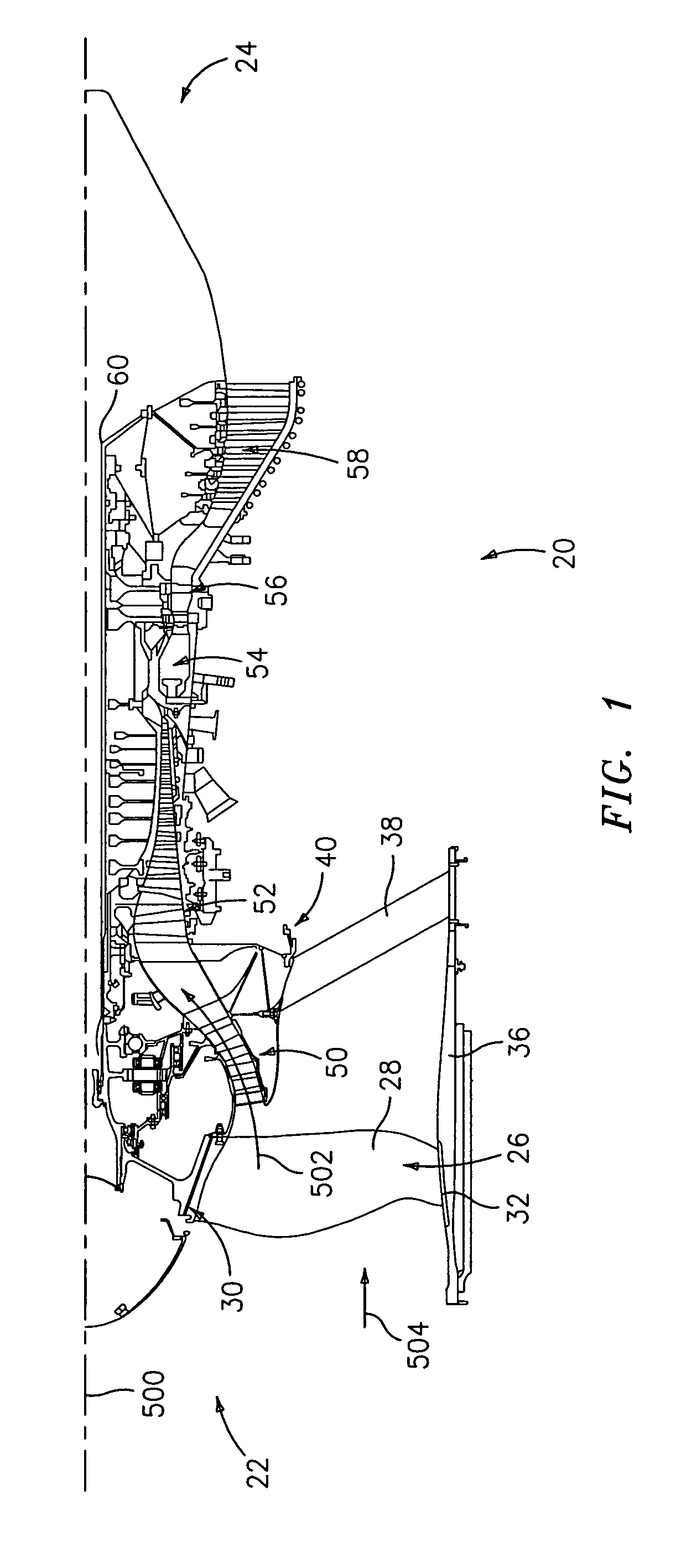
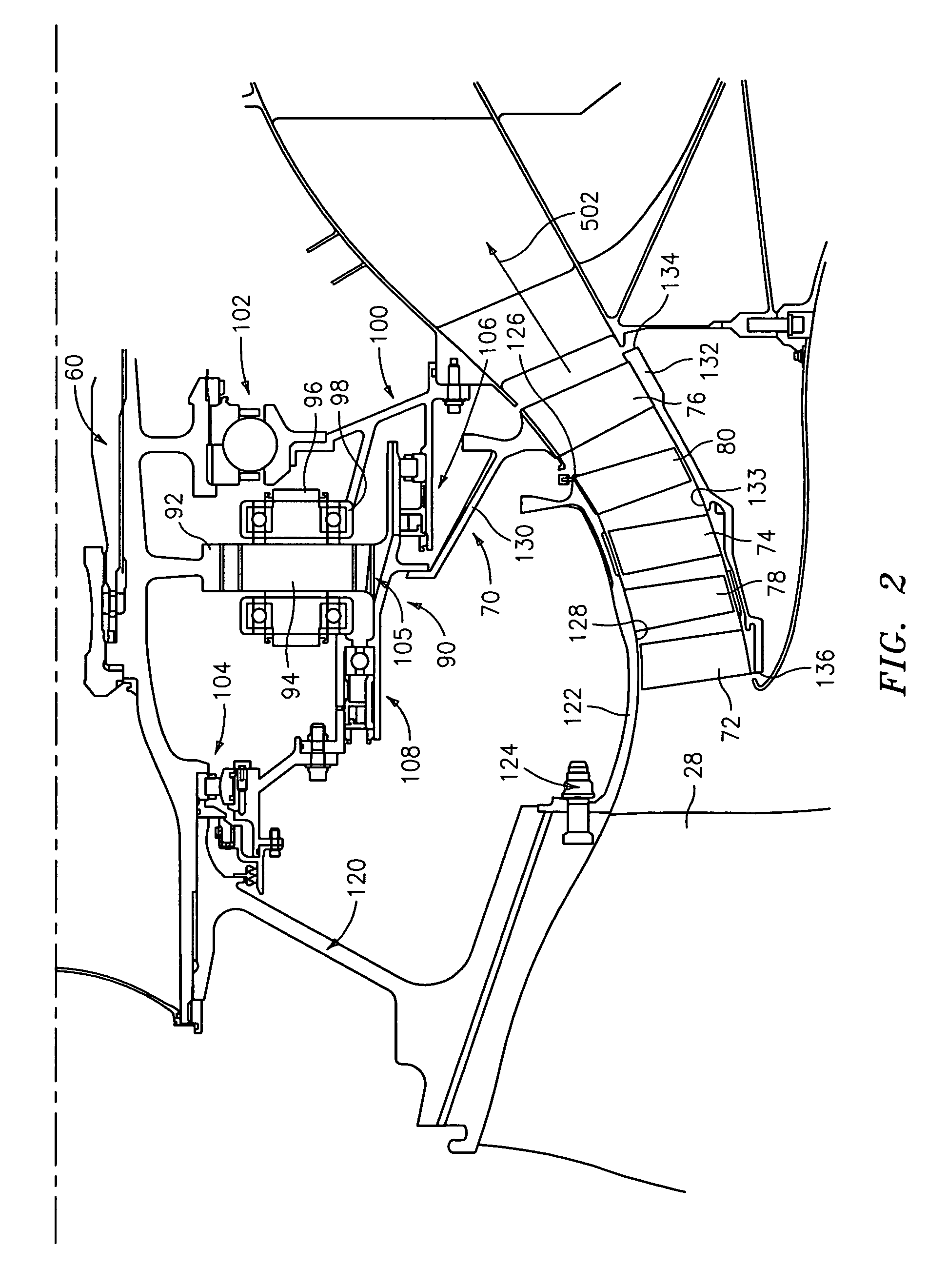
[0011]FIG. 1 shows a turbofan engine 20 having a central longitudinal axis 500. The engine has a core flowpath 502 and a bypass flowpath 504. The engine has a forward / inlet / upstream end 22 and an aft / outlet / downstream end 24. At upstream ends of the core and bypass flowpaths, the engine has a fan 26 comprising a circumferential array of blades 28 extending from inboard platforms 30 to outboard tips 32. The exemplary tips are closely spaced apart from the inboard surface of a shroud 36. The shroud may be held by a circumferential array of struts 38 extending from a structural case 40.

[0012]Proceeding downstream along the core flowpath 502, the engine has a low pressure compressor (LPC) section 50, a high pressure compressor (HPC) section 52, a combustor section 54, a high pressure turbine (HPT) section 56, and a low pressure turbine (LPT) section 58. The exemplary engine includes a low speed spool shaft 60. An exemplary high speed spool may be formed as a rotor stack (e.g., without a...


PUM


Abstract

A counter-rotating blade stage in lieu of a stator stage may compensate for relatively low rotational speed of a gas turbine engine spool. A first spool may have at least two compressor blade stage and at least two turbine blade stage. A combustor is located between the at least two compressor blade stage and the at least two turbine blade stage along a core flowpath. The at least two counter-rotating compressor blade stage is interspersed with the first spool at least two compressor blade stage. A transmission couples the at least two additional compressor blade stage to the first spool for counter-rotation about the engine axis.

Description

BACKGROUND OF THE INVENTION[0001]The invention relates to gas turbine engines. More particularly, the invention relates to low pressure compressor sections of multi-spool turbofan engines.[0002]A gas turbine engine may have one or more spools. Each spool may, for example, include the blades of associated compressor and turbine sections and a connecting shaft. Two- and three-spool engines are known. An exemplary two-spool engine included low and high speed spools. At cruise conditions, exemplary low spool speeds are 2000-7000 revolutions per minute (RPM) while exemplary high spool speeds are 9000-21000 RPM. The low spool includes low speed / pressure compressor and turbine (LPC and LPT) blades while the high spool includes high speed / pressure compressor and turbine (HPC and HPT) blades. A core flowpath through the engine may sequentially pass through the LPC, HPC, combustor, HPT, and LPT.[0003]In a turbofan engine, a fan drives air along a bypass flowpath. In many engines, the fan may ...

Claims


Application Information

Patent Timeline
Patent Type & Authority Patents(United States)
IPC IPC(8): F02K3/00
CPCF02C3/067F02C3/107F02K3/072F05D2260/40311F05D2260/40
Inventor MERRY, BRIAN D.SUCIU, GABRIEL L.NIKKANEN, JOHN P.
Owner RTX CORP
Learn More