Control device for hybrid vehicle

a control device and hybrid technology, applied in the direction of electric control, gearing, instruments, etc., can solve the problems of reducing the number of engine revolutions once, and sometimes uncomfortable feeling, and achieve the effect of suppressing drivability deterioration and reducing engine torqu

Inactive Publication Date: 2011-05-31
TOYOTA JIDOSHA KK
View PDF16 Cites 7 Cited by
  • Summary
  • Abstract
  • Description
  • Claims
  • Application Information

AI Technical Summary

Benefits of technology

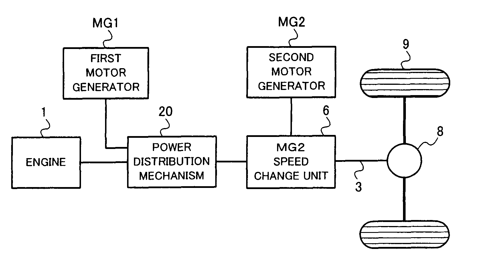
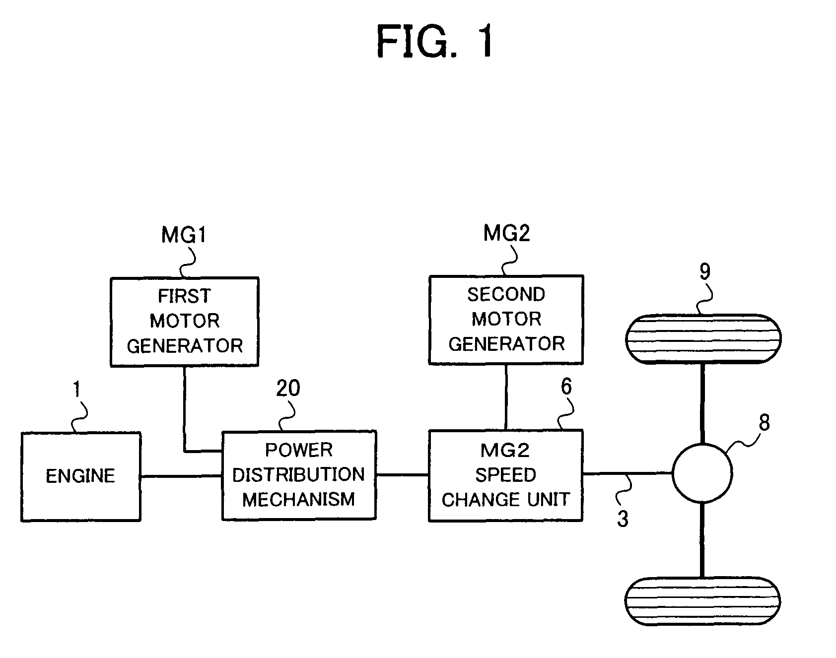
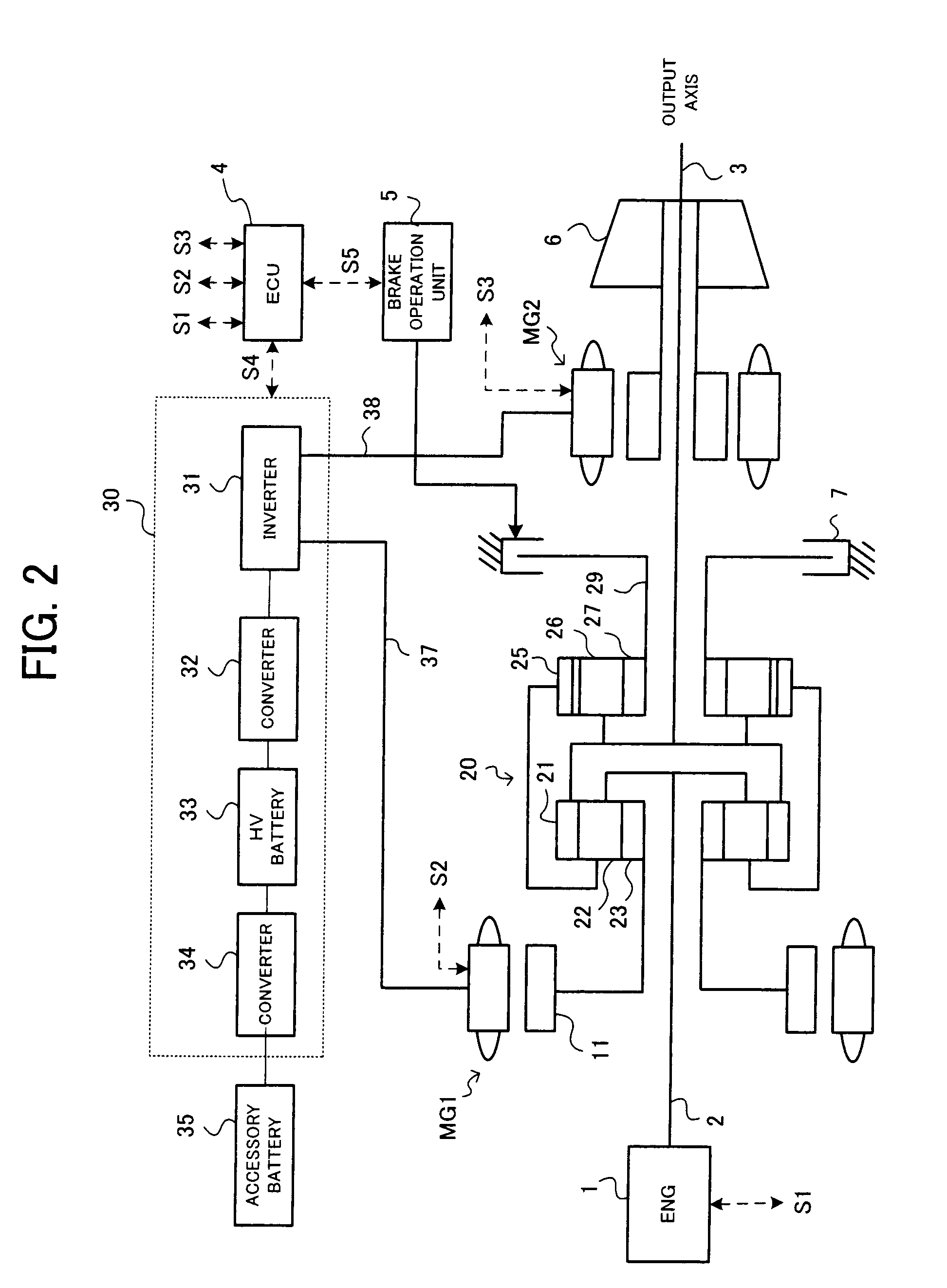
[0016]The control device for the hybrid vehicle according to the present invention is mounted on the hybrid vehicle including the engine and the motor generator as the driving source and capable of switching at least two modes, i.e., the infinite variable speed mode and the fixed gear ratio mode.
[0017]When the speed gear is shifted from the infinite variable speed mode to the fixed gear ratio mode, the first speed change control to maintain the number of revolutions equal to or larger than the number of engine revolutions at the time of setting the infinite variable speed mode and reduce the engine torque to shift the speed gear in the fixed gear ratio mode is executed. Thereby, when the speed gear is shifted from the infinite variable speed mode to the fixed gear ratio mode, it becomes possible to appropriately suppress the drivability deterioration caused due to the change of the number of engine revolutions.

Problems solved by technology

For example, when the speed gear is shifted from the fixed gear ratio mode to the infinite variable speed mode and acceleration is executed, the number of engine revolutions decreases once, and uncomfortable feeling sometimes occurs.

Method used


Image

  • Control device for hybrid vehicle
  • Control device for hybrid vehicle
  • Control device for hybrid vehicle

Examples


first embodiment

[0052]First, a description will be given of the speed change control according to a first embodiment. The speed change control according to the first embodiment corresponds to the control executed at the time of the speed change from the infinite variable speed mode to the fixed gear ratio mode. The speed change control according to the first embodiment is executed by the above-mentioned ECU 4.

[0053]FIG. 5 is a diagram for explaining the speed change control according to the first embodiment. In FIG. 5, the horizontal axis shows the number of engine revolutions, and the vertical axis shows the engine torque. An arrow C1 shows a course of the operation point in the case of executing the normal speed change control, and an arrow C2 shows a course of the operation point in the case of executing the high revolution maintaining speed change control. It is prescribed that the same reference numerals as those shown in FIG. 4 have the same meanings, and explanations thereof are omitted.

[005...

second embodiment

[0072]Next, a description will be given of the speed change control according to a second embodiment. The speed change control according to the first embodiment is the control executed at the time of performing the speed change from the infinite variable speed mode to the fixed gear ratio mode. Meanwhile, the speed change control according to the second embodiment is the control executed at the time of performing the speed change from the fixed gear ratio mode to the infinite variable speed mode. The speed change control according to the second embodiment is also executed by the ECU 4.

[0073]FIG. 8 is a diagram for explaining the speed change control according to the second embodiment. In FIG. 8, the horizontal axis shows the number of engine revolutions, and the vertical axis shows the engine torque. An arrow E1 shows the course of the operation point in such a case that the normal speed change control is executed, and an arrow E2 shows the course of the operation point in such a ca...


PUM


Abstract

The control device for the hybrid vehicle is mounted on the hybrid vehicle including the engine and the motor generator as the driving source and capable of switching at least two modes, i.e., the infinite variable speed mode and the fixed gear ratio mode. When the speed change is performed from the infinite variable speed mode to the fixed gear ratio mode, the first speed change control to maintain the number of revolutions equal to or larger than the number of engine revolutions at the time of setting the infinite variable speed mode and reduce the engine torque to shift the speed gear in the fixed gear ratio mode is executed. Thereby, when the speed change is performed from the infinite variable speed mode to the fixed gear ratio mode, it becomes possible to appropriately suppress the drivability deterioration caused due to the change of the number of engine revolutions.

Description

TECHNICAL FIELD[0001]The present invention relates to a control device preferred for a hybrid vehicle.BACKGROUND ART[0002]There is known a hybrid vehicle including a power source such as an electromotor and a motor generator, in addition to an engine. In the hybrid vehicle, while the engine operates as efficiently as possible, excess and deficiency of a driving force and an engine braking force are adjusted by the electromotor and / or the motor generator.[0003]As for the above hybrid vehicle, there is disclosed an example of a speed change mechanism capable of operating with switching an infinite variable speed mode and a fixed gear ratio mode in Patent Reference 1. Concretely, a power distribution mechanism including four revolution components is formed by combining two planetary gear mechanisms, and the four revolution components are connected to an engine, a first motor generator, an output axis and a brake, respectively. In such a state that the brake is released, the number of r...

Claims


Application Information

Patent Timeline
Patent Type & Authority Patents(United States)
IPC IPC(8): B60K1/00B60K6/20B60K6/365B60K6/445B60K6/547B60W10/04B60W10/06B60W10/08B60W10/10B60W10/101B60W20/00F02D29/00F02D29/02F02D45/00
CPCB60K6/365B60K6/445B60K6/547B60W10/06B60W10/08B60W20/00B60W10/115B60K1/02Y02T10/6239B60W2710/0666F16H2037/0866F16H2200/2007Y02T10/6286Y02T10/62B60W20/30
Inventor FUKUMURA, MITSUMASA
Owner TOYOTA JIDOSHA KK
Why Eureka
Try Eureka