
Electronic engine control device

a control device and electronic technology, applied in the direction of electric control, ignition automatic control, machines/engines, etc., can solve the problems of operator uneasy feeling and engine torque drop

Inactive Publication Date: 2005-11-15
YAMAHA MOTOR CO LTD
View PDF22 Cites 18 Cited by
  • Summary
  • Abstract
  • Description
  • Claims
  • Application Information

AI Technical Summary

Benefits of technology

[0007]Known electronic engine control devices respond to a system failure by performing a fail-safe operation in which engine torque is quickly decreased, such as an action of stopping fuel supply to the engine. However, as far as two-wheeled vehicles are concerned, a rapid decrease in engine torque would cause the operator to have an uneasy feeling because of the abrupt change in engine torque and a resulting abrupt change in vehicle speed. In view of the foregoing, an object of this invention is to provide an engine control device that performs a fail-safe operation in response to a system failure or error to gradually reduce the engine torque without causing the operator to experience uneasy feeling.

Problems solved by technology

However, as far as two-wheeled vehicles are concerned, a rapid decrease in engine torque would cause the operator to have an uneasy feeling because of the abrupt change in engine torque and a resulting abrupt change in vehicle speed.

Method used


Image

  • Electronic engine control device
  • Electronic engine control device
  • Electronic engine control device

Examples


Embodiment Construction

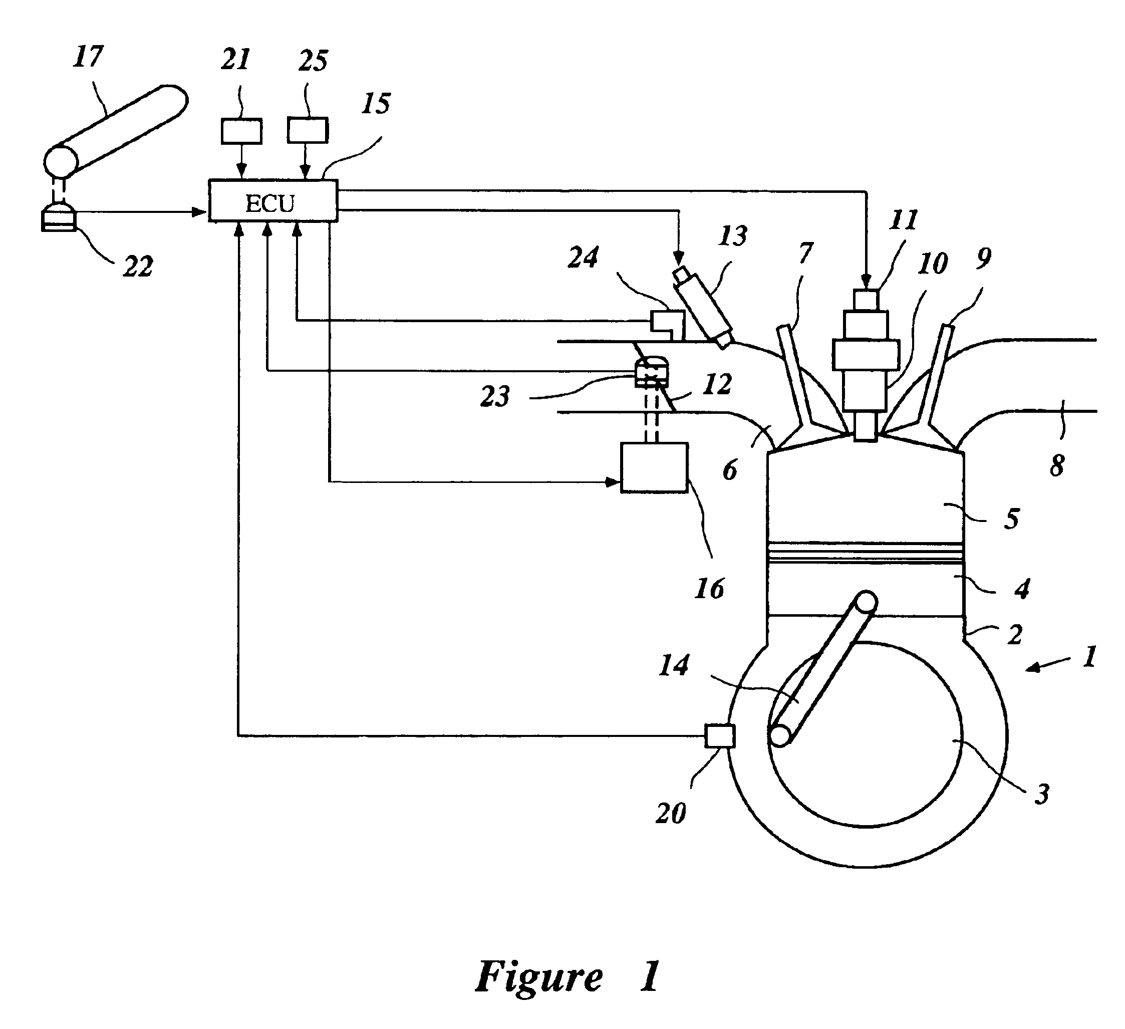
[0028]A preferred embodiment of the present invention will be described below in connection with the accompanying drawing figures.

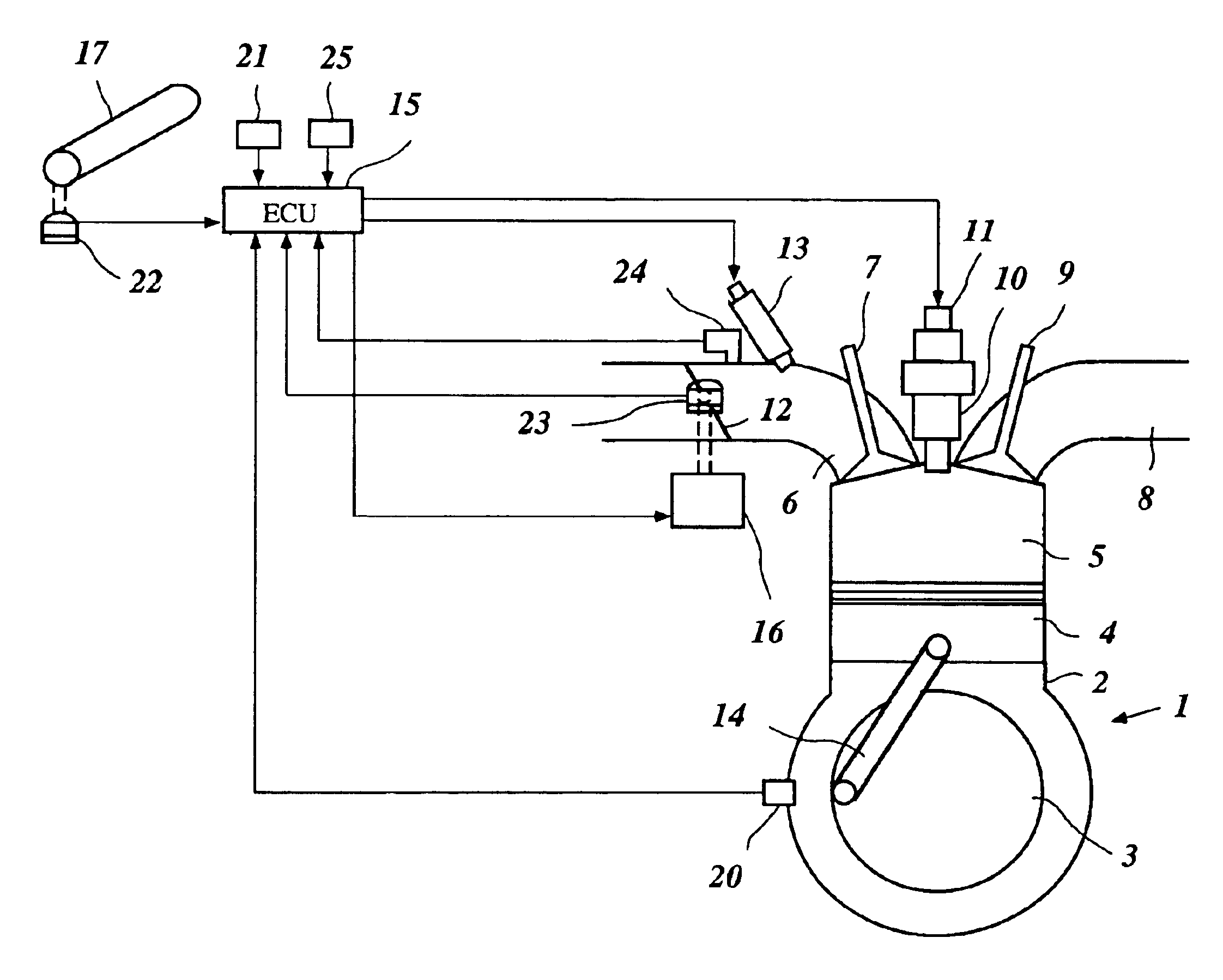
[0029]FIG. 1 is a schematic structural diagram showing an example of an engine for a motorcycle and its control device. In the illustrated embodiment, the engine 1 is a four-cylinder four-stroke engine. Each cylinder of the engine comprises a cylinder body 2, a crank shaft 3, a piston 4, a connecting rod 14, a combustion chamber 5, an intake pipe 6, an intake valve 7, an exhaust pipe 8, an exhaust valve 9, an ignition plug 10, and an ignition coil 11.

[0030]The intake pipe 6 includes a throttle valve 12 that is adapted to be opened and closed in response to the opening of an accelerator 17, which for a motorcycle or the like, is positioned on the handlebars. The intake pipe 6 also includes an injector 13 positioned on the downstream side from the throttle valve 12. The injector 13 operates as a fuel injection device. The injector 13 is connected to a filte...


PUM


Abstract

An electronic engine control unit for a motorcycle or other two-wheeled vehicle gradually decreases engine torque at the time of a failure so as to eliminate an uneasy feeling that an operator might experience if the engine torque were to be reduced abruptly. When a failure is detected, a throttle valve is closed gradually by initially closing the valve quickly and then slowly closing the valve so as to obtain a smooth decrease in engine torque. In addition, the ignition timing is changed gradually toward retardation to gradually decrease engine torque. Alternatively, the ignition pulses to the cylinders are thinned out gradually to cause a gradual decrease in engine torque. As a further alternative in the case of a multi-cylinder engine, the ignition pulses are stopped on a cylinder-by-cylinder basis to cause a gradual decrease in engine torque.

Description

PRIORITY INFORMATION[0001]This application is based on and claims priority under 35 U.S.C. §119 to Japanese Patent Application No. 2001-260440, filed on Aug. 29, 2001, the entire contents of which are hereby expressly incorporated by reference herein.BACKGROUND OF THE INVENTION[0002]1. Field of the Invention[0003]This invention relates to an electronic control device for controlling an engine, and is suited particularly for controlling a fuel-injected engine to provide a safe engine shutdown procedure in response to a failure or an error in an engine management system or a vehicle sensor.[0004]2. Description of the Related Art[0005]Two-wheeled vehicles (e.g., motorcycles) typically incorporate internal combustion engines to provide power to propel the two-wheeled vehicles in a variety of popular applications. In addition, the engines in two-wheeled vehicles incorporate sophisticated engine management systems to ensure maximum performance, increased fuel economy, and cleaner exhaust ...

Claims


Application Information

Patent Timeline
IPC IPC(8): F02D37/00F02D41/22F02D37/02F02D11/10F02D9/02F02D45/00F02P5/15F02P9/00F02P11/04F02P11/06
CPCF02D11/107F02D37/02F02D41/22F02P9/005F02P11/06F02D2009/0277F02D2009/0284F02D2011/102F02D2041/227F02D2200/0404F02D2200/602F02D2250/18
Inventor SAMOTO, HARUHIKOKISHI, TOMOAKI
Owner YAMAHA MOTOR CO LTD
Learn More