Vehicle control apparatus

a technology of vehicle control and control apparatus, which is applied in the direction of electric control, machines/engines, instruments, etc., can solve the problems of increased development costs of vehicles, difficult to reduce engine torque by an amount equivalent to the inertia torque, and shift shock, etc., to suppress shift shock, reduce engine torque, and increase engine torque

Active Publication Date: 2013-03-28
SUBARU CORP
View PDF4 Cites 7 Cited by
  • Summary
  • Abstract
  • Description
  • Claims
  • Application Information

AI Technical Summary

Benefits of technology

[0009]An object of the present invention is to simplify matching work to thereby reduce the development costs of a vehicle.
[0013]In the vehicle control apparatus of the present invention, the engine control means may reduce the engine torque when the continuously variable transmission is shifted to an acceleration side, and may increase the engine torque when the continuously variable transmission is shifted to a deceleration side.
[0014]According to the present invention, the upper limit of the inertia torque to be absorbed by the engine is calculated on the basis of the setting state of the driving mode, and then the upper-limit shift speed during the speed shifting is set on the basis of the upper limit. Hence, shift speed matching power characteristics in each driving mode may easily be set while also suppressing shift shock. This may simplify matching work in a development stage and may reduce development costs of a vehicle.

Problems solved by technology

The inertia torque acts in a direction to accelerate the primary pulley, thereby temporarily increasing output torque from the continuously variable transmission to cause shift shock.
However, in a coasting state in which the engine torque is very small, it is difficult to reduce the engine torque by an amount equivalent to that of the inertia torque.
However, setting of the range of reduction in the shift speed corresponding to each driving mode involves complicated matching work which results in increased development costs of the vehicle.

Method used


Image

  • Vehicle control apparatus
  • Vehicle control apparatus
  • Vehicle control apparatus

Examples


Embodiment Construction

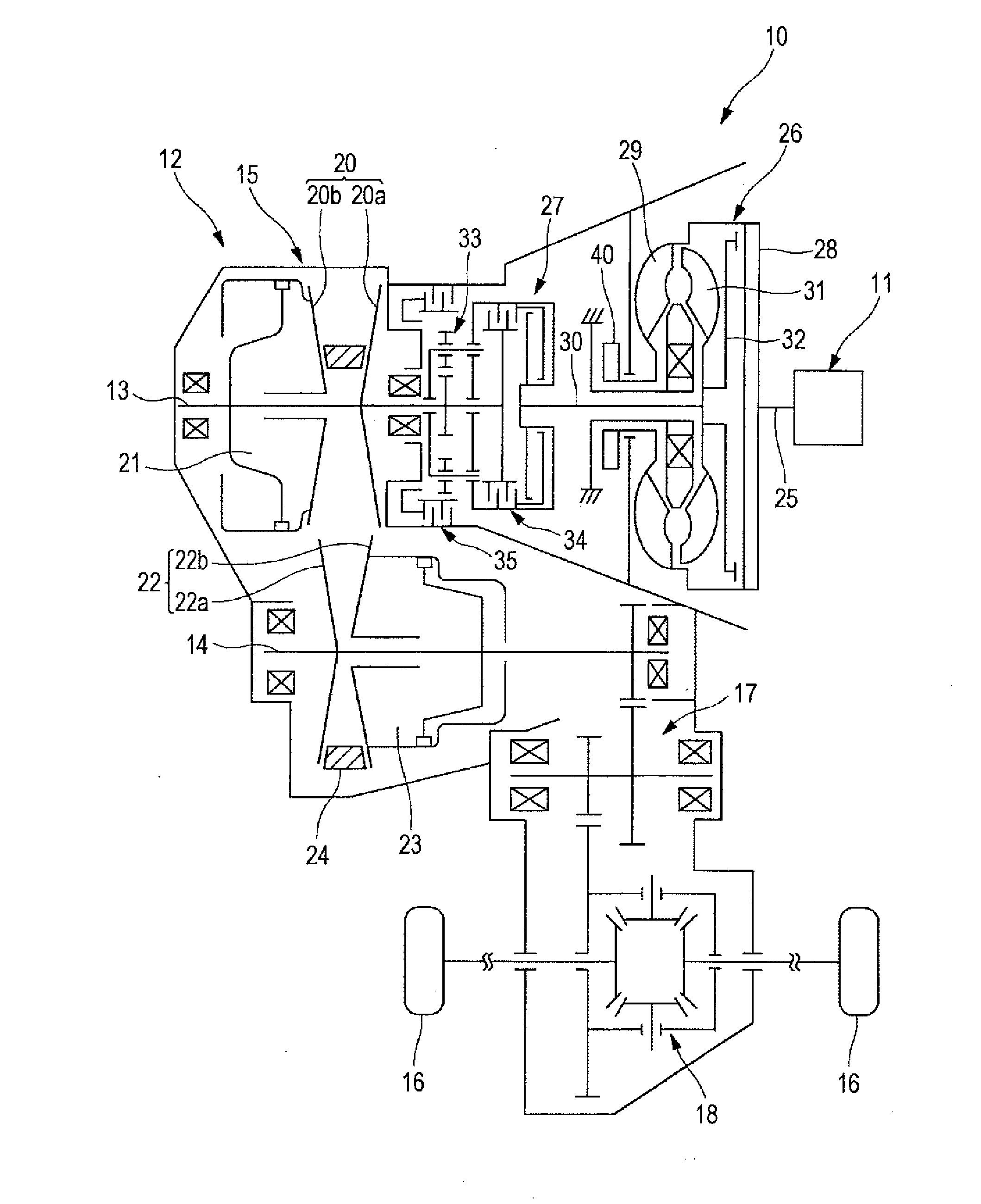
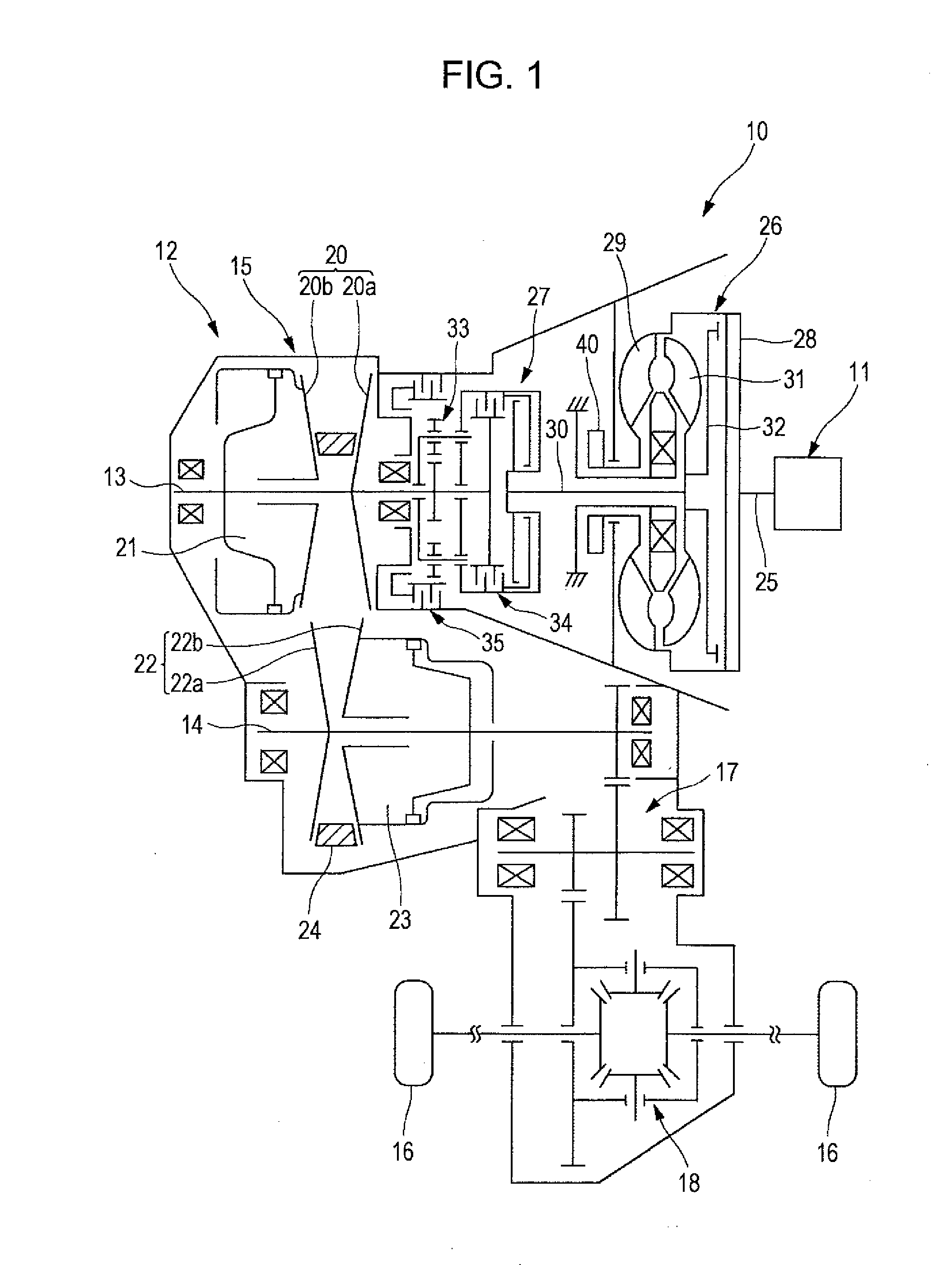
[0033]Embodiments of the present invention will be described in detail below with reference to the accompanying drawings. FIG. 1 is a skeleton diagram illustrating a power unit 10 to be installed in a vehicle. The power unit 10 is controlled by a vehicle control apparatus of an embodiment of the present invention. As illustrated in FIG. 1, the power unit 10 includes an engine 11, which is a power source, and a continuously variable transmission 12 connected to the engine 11. The continuously variable transmission 12 includes a primary shaft 13 driven by the engine 11 and a secondary shaft 14 arranged in parallel with the primary shaft 13. A transmission mechanism 15 is provided between the primary shaft 13 and the secondary shaft 14. A reduction mechanism 17 and a differential mechanism 18 are provided between the secondary shaft 14 and drive wheels 16.

[0034]The primary shaft 13 is provided with a primary pulley 20. The primary pulley 20 includes a fixed sheave 20a and a movable she...


PUM


Abstract

In a vehicle control apparatus, an engine torque calculating unit calculates a developing engine torque Te, and a torque increase / decrease amount calculating unit calculates a torque increase or decrease amount Tmax of an engine which can be increased or decreased. A mode coefficient setting unit sets a mode coefficient k corresponding to a driving mode, and an allowable inertia calculating unit multiplies the torque increase or decrease amount Tmax by the mode coefficient k to calculate an allowable inertia torque Timax. A shift speed calculating unit calculates a shift speed V1 of a continuously variable transmission at which the allowable inertia torque Timax is generated, and an upper-limit shift speed setting unit sets an upper-limit shift speed V2 based on the shift speed V1. A shift control unit performs shift control of the continuously variable transmission at a shift speed not exceeding the upper-limit shift speed V2.

Description

CROSS-REFERENCE TO RELATED APPLICATIONS[0001]The present application claims priority from Japanese Patent Application No. 2011-210416 filed on Sep. 27, 2011, the entire contents of which are hereby incorporated by reference.BACKGROUND OF THE INVENTION[0002]1. Field of the Invention[0003]The present invention relates to a vehicle control apparatus that includes a power unit having an engine and a continuously variable transmission connected to the engine, and a power unit controller for switching the power characteristics of the power unit in accordance with the driving mode.[0004]2. Description of the Related Art[0005]A continuously variable transmission provided in a power transmission system of a vehicle includes a primary pulley mounted on an input shaft, a secondary pulley mounted on an output shaft, and a drive chain wrapped around these pulleys. In such a continuously variable transmission, any speed ratio can be set by regulating groove widths of the pulleys. Hence, the speed...

Claims


Application Information

Patent Timeline
Patent Type & Authority Applications(United States)
IPC IPC(8): B60W10/101
CPCF02D29/02F16H61/66259F02D41/023F02D2400/12F16H61/04B60W2510/0695F16H2059/085F16H2059/084F16H2059/0226F16H63/502
Inventor AJIMOTO, KEISUKE
Owner SUBARU CORP
Why Eureka
Try Eureka