
Guidewire loader apparatus and method

a loader and guidewire technology, applied in the field of medical devices, can solve the problems of difficult guidewire routing into the guidewire lumen, slippery surfaces, and further complicated process, and achieve the effect of easing the engagement of the medical devi

Inactive Publication Date: 2011-05-31
ABBOTT LAB INC
View PDF19 Cites 13 Cited by
  • Summary
  • Abstract
  • Description
  • Claims
  • Application Information

AI Technical Summary

Benefits of technology

[0008]To address the above-mentioned problems, the present invention provides a tool for aligning and facilitating insertion of a guidewire into a guidewire lumen of a medical device. The tool includes a handle having a portion sized to receive a medical device therein and a lumen aligned with the medical device receiving portion to direct a guidewire into a lumen. The lumen may further include a tapered portion on each end to ease engagement of the medical device and the guidewire.

Problems solved by technology

Routing the guidewire into the guidewire lumen proves to be difficult for many reasons.
This process may be further complicated by coatings applied to either the guidewire or the catheter, or both, which may make the surfaces slippery thereby hindering the process.
However, such flexible tips are difficult to use with catheters because they are not stiff enough to be easily disposed within the guidewire lumen without severely bending and possibly kinking the catheter.

Method used


Image

  • Guidewire loader apparatus and method
  • Guidewire loader apparatus and method
  • Guidewire loader apparatus and method

Examples


Embodiment Construction

[0030]While the present invention will be described with reference to a few specific embodiments, the description is illustrative of the invention and is not to be construed as limiting the invention. Various modifications to the present invention can be made to the preferred embodiments by those skilled in the art without departing from the true spirit and scope of the invention as defined by the appended claims. It will be noted here that for a better understanding, like components are designated by like reference numerals throughout the various figures.

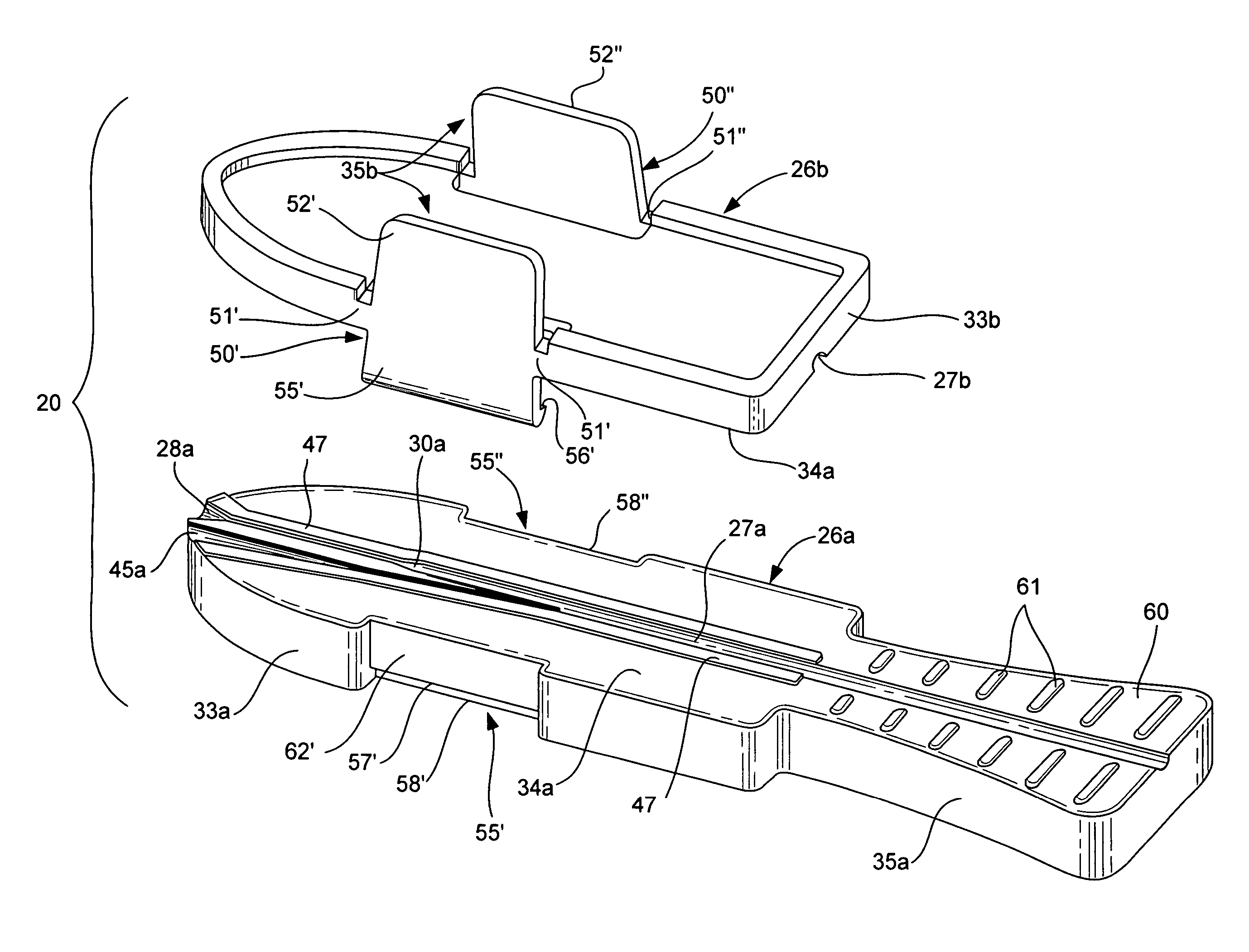
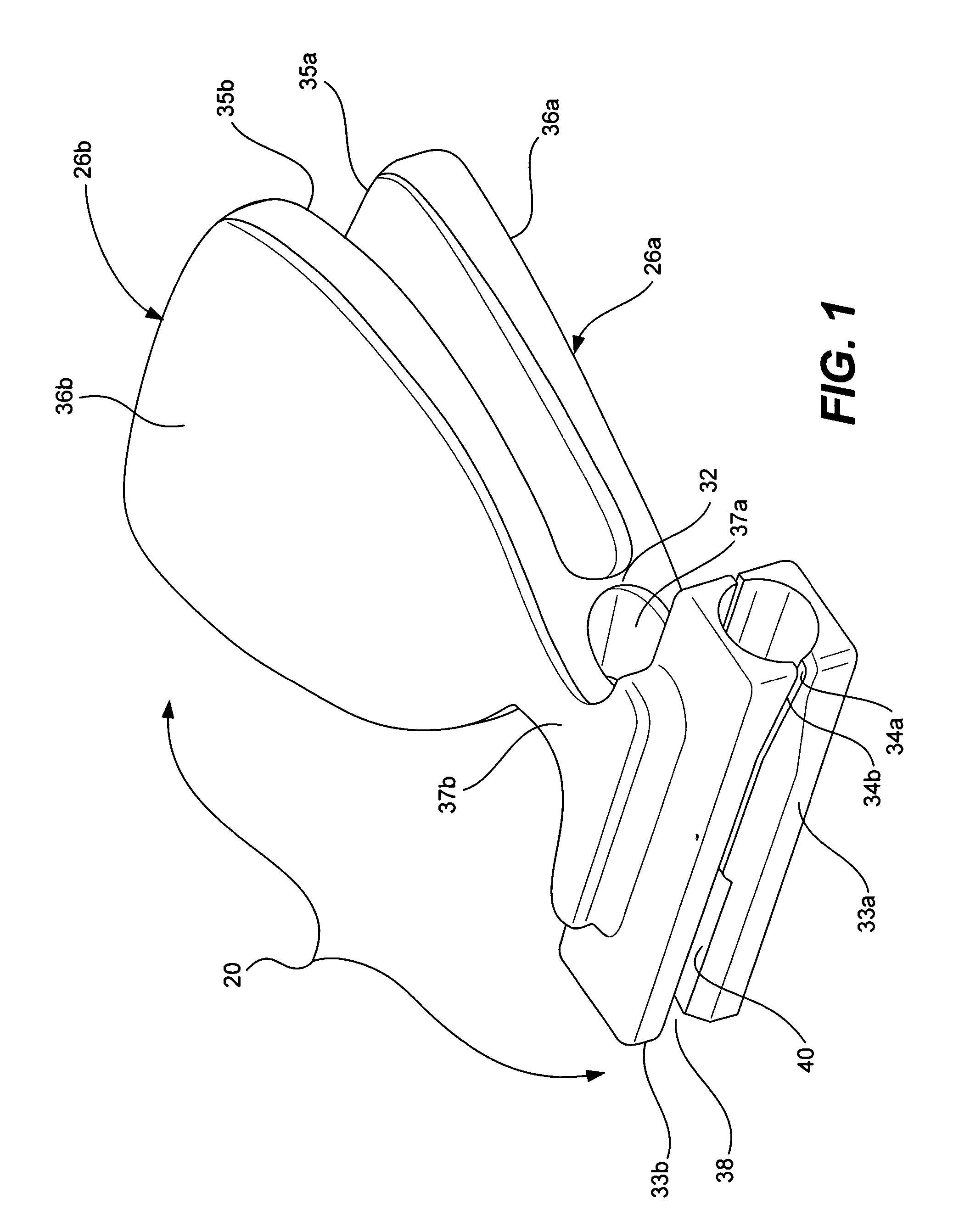
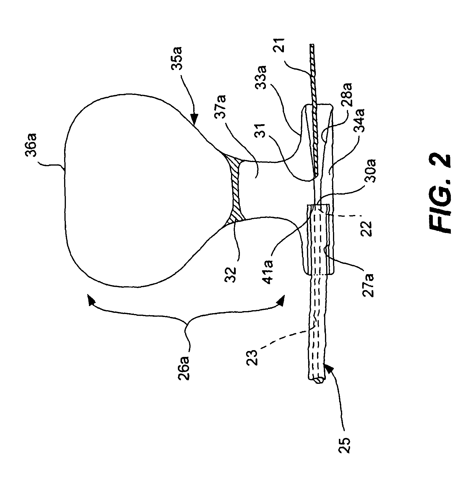
[0031]Referring now to a first embodiment of FIGS. 1-3 and a second embodiment of FIGS. 4-7, a guidewire loader apparatus, generally designated 20, is provided for loading a guidewire 21 into a first lumen opening 22 of a first guidewire lumen 23 of a medical device 25. The guidewire loader apparatus 20 includes a first member 26a defining a respective medical device receiving portion 27a and a respective first guidewire receiving ...


PUM


Abstract

A guidewire loader apparatus is provided for loading a guidewire into a lumen opening of a guidewire lumen of a medical device. The loader apparatus includes a first member defining a respective medical device receiving portion and a respective guidewire receiving portion in communication therewith via a respective interface portion. The loader apparatus further includes a second member configured for placement in an opposed relationship to the first member. The second member defines a respective medical device receiving portion and a respective guidewire receiving portion in communication therewith at a respective interface portion. The first member and the second member cooperatively associate with one another between a first position and a second position. In the first position, the medical device can be positioned into at least one respective medical device receiving portion. In the second position, the respective device receiving portions cooperate to align and support the medical device in a manner placing the lumen opening of the medical device substantially adjacent to the cooperating, respective interface portions. This permits aligned sliding receipt of an end of the guidewire into the cooperating, respective guidewire receiving portions, through the cooperating respective interface portions and into the lumen opening of the medical device.

Description

RELATED APPLICATION DATA[0001]The present application claims priority under 35 U.S.C. §119 to U.S. Provisional Application Ser. No. 60 / 678,145, naming Zung as the inventor, filed May 5, 2005, and entitled GUIDEWIRE LOADER, the entirety of which is incorporated herein by reference for all purposes.FIELD OF THE INVENTION[0002]The present invention relates to medical devices in general, and in particular to a device for facilitating the loading of guidewires into medical devices.BACKGROUND OF THE INVENTION[0003]As an alternative to invasive-type surgeries whereby a physician creates an incision to access a desired location in the patient's body, many minimally invasive surgeries and in vivo examinations are being performed using catheters that are inserted into a patient's body. With a catheter in place, medical devices are routed through a lumen in the catheter in order to obtain tissue samples, perform a surgical procedure or diagnose tissue in a patient's body.[0004]To insert a cath...

Claims


Application Information

Patent Timeline
Patent Type & Authority Patents(United States)
IPC IPC(8): A61B5/00A61M39/10A61M39/00A61M25/18A61M25/16A61M25/00A61B6/00
CPCA61M25/09041A61M2025/09116
Inventor JONES, ANDREWZUNG, MICHAEL
Owner ABBOTT LAB INC
Learn More