Electro-optic media produced using ink jet printing

a technology of ink jet printing and electrophoretic media, which is applied in the field of electrophoretic media produced using ink jet printing, can solve the problems of inadequate service life of gas-based electrophoretic media, unable to meet the needs of the user, so as to reduce the cost and production lead time, and increase the cost

Active Publication Date: 2011-05-31
E INK CORPORATION
View PDF260 Cites 172 Cited by
  • Summary
  • Abstract
  • Description
  • Claims
  • Application Information

AI Technical Summary

Benefits of technology

[0028]In one form of this process, the electrophoretic medium is applied to a backplane containing at least one pixel electrode. Typically in such a process, the substrate comprises at least first and second pixel electrodes and a first electrophoretic medium is ink jet printed on the first pixel electrode and a second electrophoretic medium, having at least one optical state different from all the optical states of the first electrophoretic medium, is ink jet printed on the second pixel electrode. It is necessary to control the deposition of the various electrophoretic media so as to align them with the pixel electrodes, but in some cases it may not be necessary to align a specific electrophoretic medium with a specific electrode or set of electrodes. For example, consider a backplane on which are deposited three different encapsulated electrophoretic media having respectively red / white, green / white and blue / white extreme optical states, with each of the three media being coated on every third column of pixels in a two-dimensional row / column array of pixels. Provided that the stripes of each medium are accurately aligned with the columns of pixels, it is not necessary that the same medium always be deposited on (say) column 100 of pixels; provided that the same medium is deposited on column 100, column 103, column 106 etc., the final assignment of column 100 to be a red, green or blue column can be handled by the drive electronics or software. The deposition of the various electrophoretic medium may be simultaneous or sequential. In a preferred form of the process, the first electrophoretic medium is ink jet printed on the first pixel electrode with its continuous phase in a fluid form, and then subjected to conditions effective to convert the continuous phase to a solid form, thereby forming a coherent layer of the first electrophoretic medium on the first pixel electrode, and thereafter the second electrophoretic medium is ink jet printed on the second pixel electrode. To assist in depositing the electrophoretic media in alignment with the electrodes, the substrate may be provided with at least one fiducial mark and the printing of the electrophoretic medium may be effected at least one predetermined location relative to the at least one fiducial mark. Alternatively, the substrate may be mounted at a predetermined location on a stage (for example, apertures on the substrate may be engaged with projections on the stage) and the printing of the electrophoretic medium be effected at least one predetermined location relative to the stage.
[0087]A further aspect of the invention relates to the ink jet printing of electrodes and / or conductors on to a layer of electro-optic material. Although as discussed above, in most cases it is common practice to form an electro-optic display by laminating a layer of electro-optic material to a backplane containing one or more electrodes, there are certain types of display where it may be advantageous to form the electrodes directly on to the electro-optic material. For example, it is known to use direct drive electro-optic displays (displays in which each pixel, which is typically of substantial size, is provided with a separate conductor which can be used to control the voltage applied to the pixel) as “animated” advertising signs in which the voltages on the pixels are controlled so that the sign cycles through a series of differing appearances. Each type of direct drive sign requires a different arrangement of pixels and hence of pixel electrodes, and if the pixel electrodes are produced in the conventional manner by etching a layer of metal on a backplane, each type of direct drive sign requires the preparation of at least one mask. Similarly, if the pixel electrodes are printed by conventional processes, for example using a printing roller, each type of direct drive sign requires the preparation of a new roller. The need for such masks or rollers increases the cost and the production lead time of direct drive signs. Ink jet printing of pixel electrodes and / or associated conductors directly on to a layer of electro-optic material avoids the need to prepare masks or printing rollers, and thus decreases costs and production lead time, since the ink jet printing can be directly controlled by a computer storing an image of the desired pattern of electrodes and / or conductors; in effect, the ink jet printing process uses a virtual, electronic mask rather than a physical one.

Problems solved by technology

Nevertheless, problems with the long-term image quality of these displays have prevented their widespread usage.
For example, particles that make up electrophoretic displays tend to settle, resulting in inadequate service-life for these displays.
Such gas-based electrophoretic media appear to be susceptible to the same types of problems due to particle settling as liquid-based electrophoretic media, when the media are used in an orientation which permits such settling, for example in a sign where the medium is disposed in a vertical plane.
Indeed, particle settling appears to be a more serious problem in gas-based electrophoretic media than in liquid-based ones, since the lower viscosity of gaseous suspending fluids as compared with liquid ones allows more rapid settling of the electrophoretic particles.

Method used


Image

  • Electro-optic media produced using ink jet printing
  • Electro-optic media produced using ink jet printing
  • Electro-optic media produced using ink jet printing

Examples


Embodiment Construction

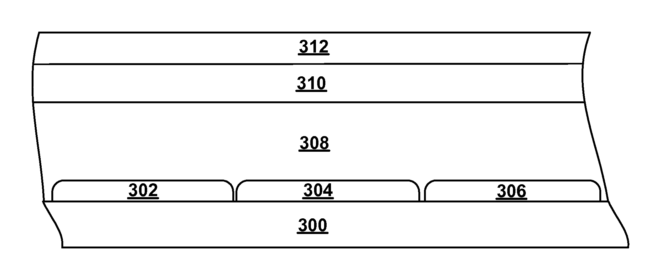
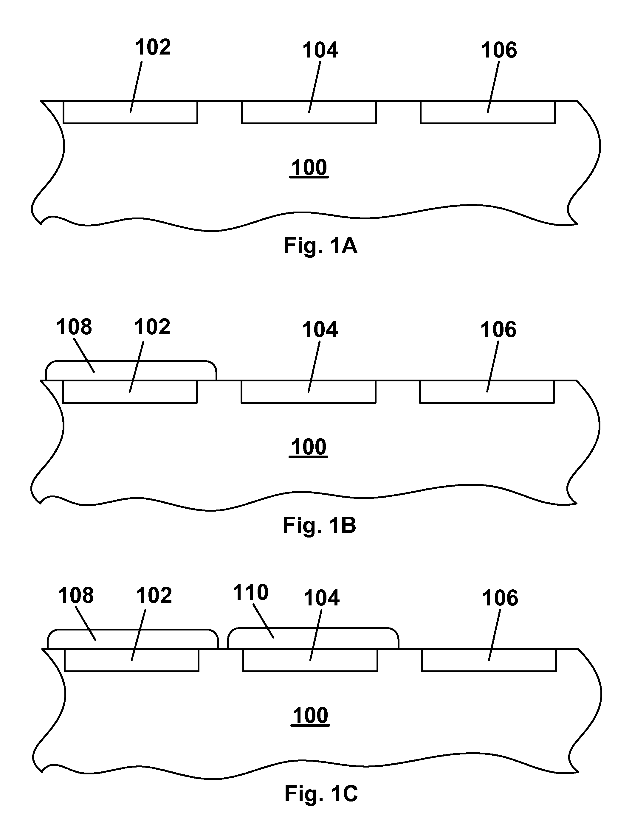
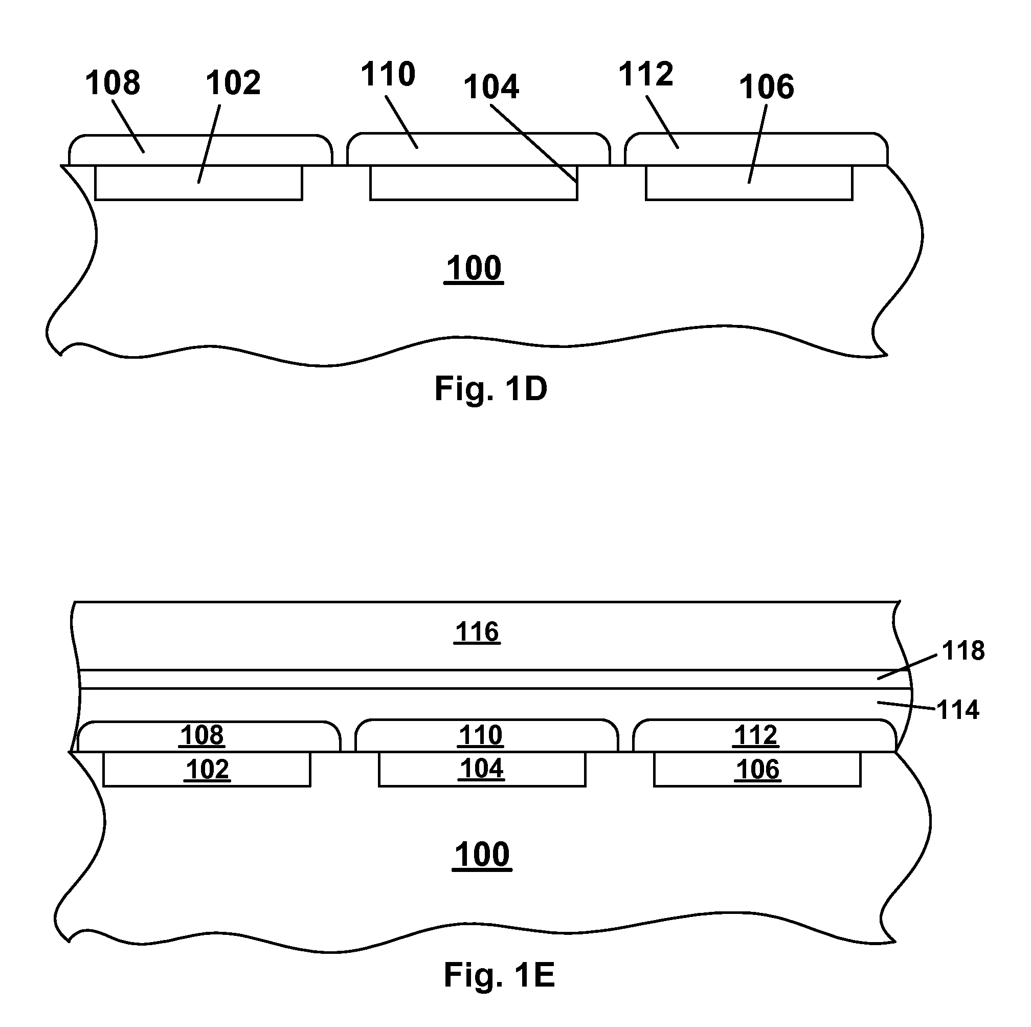
[0093]As already mentioned, the present invention provides numerous different processes in which ink jet printing is used in the production of electro-optic displays and components of such displays, especially front plane laminates and double release films. However, the numerous different processes of the invention all make use of one of the following four steps:[0094](a) ink jet printing a layer of a polymer-dispersed electrophoretic medium on a substrate;[0095](b) ink jet printing a plurality of different electro-optic media on a substrate to form a “color” electro-optic layer (in the sense of an electro-optic layer in which different areas react differently to application of an electric field);[0096](c) ink jet printing a plurality of different colored materials on a substrate to produce a color filter (which is not necessarily a full color filter); and[0097](d) ink jet printing electrodes and / or associated conductors on a layer of electro-optic material.

[0098]Various processes o...


PUM

PropertyMeasurementUnit
diameteraaaaaaaaaa
thicknessaaaaaaaaaa
thicknessaaaaaaaaaa

Abstract

Ink jet printing can be used in the production of electro-optic displays for (a) forming a layer of a polymer-dispersed electrophoretic medium on a substrate; (b) forming a color electro-optic layer; (c) forming a color filter; and (d) printing electrodes and / or associated conductors on a layer of electro-optic material.

Description

REFERENCE TO RELATED APPLICATIONS[0001]This application claims benefit of Provisional Application Ser. No. 60 / 743,653, filed Mar. 22, 2006.[0002]This application is related to:[0003](a) U.S. Pat. No. 6,982,178;[0004](b) application Ser. No. 10 / 605,024 filed Sep. 2, 2003 (Publication No. 2004 / 0155857, now U.S. Pat. No. 7,561,324); and[0005](c) U.S. Pat. No. 7,110,164, issued Sep. 19, 2006 on application Ser. No. 10 / 904,063, filed Oct. 21, 2004, which claims priority from Application Ser. No. 60 / 481,553, filed Oct. 24, 2003; Application Ser. No. 60 / 481,554, filed Oct. 24, 2003; Application Ser. No. 60 / 481,557, filed Oct. 23, 2003; Application Ser. No. 60 / 481,564, filed Oct. 27, 2003; and Application Ser. No. 60 / 520,226, filed Nov. 14, 2003.[0006]The entire contents of all the aforementioned applications, and of all other United States Patents and published and copending Applications mentioned below, are also herein incorporated by reference.BACKGROUND OF INVENTION[0007]The present inv...

Claims


Application Information

Patent Timeline
Patent Type & Authority Patents(United States)
IPC IPC(8): G02B26/00G02F1/167G02F1/1679
CPCG02B5/201G02F1/167G02F1/133516G02F2001/1676G02F1/1679
Inventor HONEYMAN, CHARLES HOWIEDANNER, GUY M.
Owner E INK CORPORATION
Why Eureka
Try Eureka