Multicolor diode-laser module

a technology of laser module and diode, which is applied in the direction of laser, laser details, instruments, etc., can solve the problem of adding significant cost to the system

Inactive Publication Date: 2011-05-31
COHERENT INC
View PDF7 Cites 10 Cited by
  • Summary
  • Abstract
  • Description
  • Claims
  • Application Information

AI Technical Summary

Problems solved by technology

This adds significant cost to a system as more lasers are added.

Method used


Image

  • Multicolor diode-laser module
  • Multicolor diode-laser module
  • Multicolor diode-laser module

Examples


Embodiment Construction

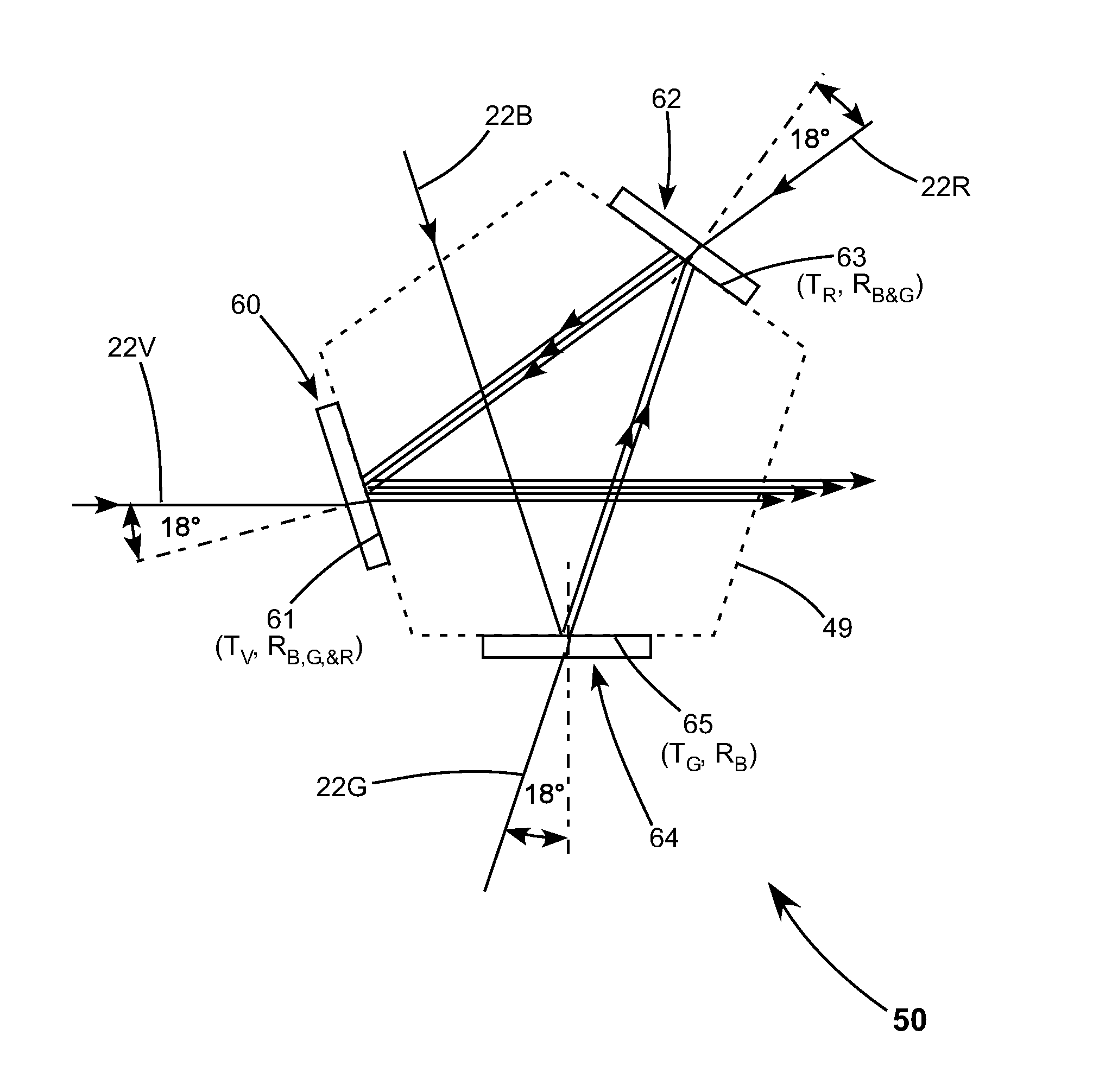
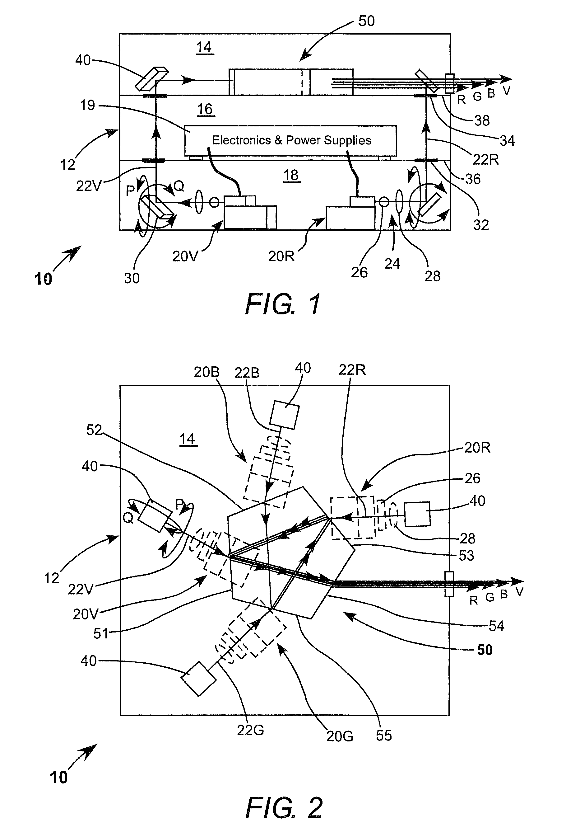
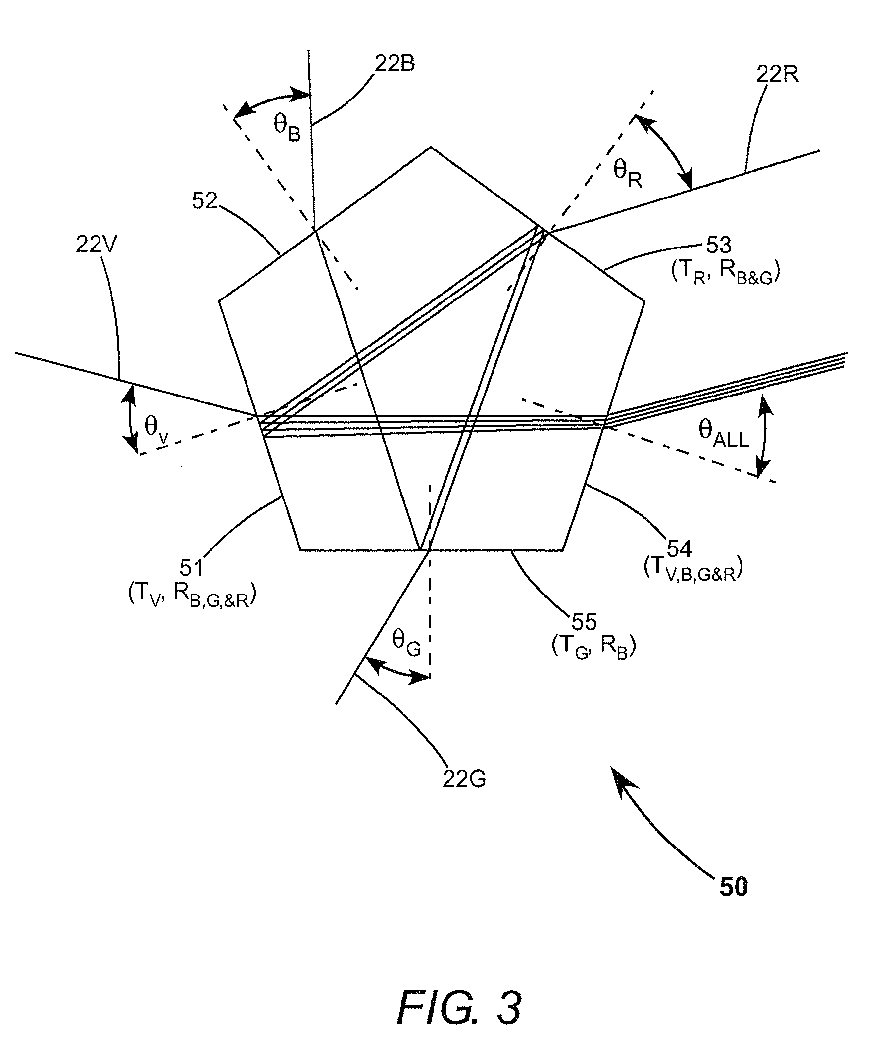
[0012]Referring now to the drawings, wherein like components are designated by like reference numerals, FIG. 1 is a side-elevation view partly in cross-section schematically illustrating one preferred embodiment 10 of a multicolor laser module in accordance with the present invention. Module 10 includes a housing 12. Housing 12 is divided into an upper compartment 14, a central compartment 16 and a lower compartment 18, with the compartments arranged one above the other. FIG. 2 is a plan view from above schematically illustrating detail of the layout of upper compartment 14 of housing 12 with components housed in lower compartment 18 indicated in phantom.

[0013]It is assumed that module 10 delivers a beam including four colors, violet (V), blue (B), green (G) and red (R). These colors, however, should not be construed as limiting the present invention to any number or value of wavelengths to be combined in a beam. Lower compartment 18 includes four lasers 20, preferably diode-lasers....


PUM


Abstract

A multi-laser module includes two compartments arranged one above the other. The lower compartment includes four lasers and four corresponding beam-steering mirrors arranged to direct corresponding laser beams into the upper compartment. The upper compartment includes a regular pentagonal prism and four other beam-steering mirrors each arranged to receive one of the laser beams and direct that beam to the prism. The beam prism has three dichroic-coated surfaces and two antireflection-coated surfaces. Each of three of the beams enter the prism via a corresponding one of the dichroic-coated surfaces. The fourth beam enters the prism via one of the antireflection coated surfaces, and all of the beams exit the prism via the other antireflection coated surface along a common path.

Description

TECHNICAL FIELD OF THE INVENTION[0001]The present invention relates in general to methods and apparatus for optical beam combining. The invention relates in particular to methods of combining four or more laser beams each thereof having a different wavelength from any other.DISCUSSION OF BACKGROUND ART[0002]There are certain applications of laser radiation that require a beam of radiation including a plurality of discrete wavelengths or colors. Such applications include flow cytometry, genomics, and confocal microscopy. As commercial lasers typically emit radiation at nominally only one wavelength, such a multicolor beam is typically provided by combining the beams of a plurality of lasers using an optical system including a plurality of dichroic-filter-coated beam combiners. The “footprint” of such a system scales with the number of colors, and hence the number of lasers required in the output beam. As the dichroic-combiners form part of a beam alignment chain, each preferably has ...

Claims


Application Information

Patent Timeline
Patent Type & Authority Patents(United States)
IPC IPC(8): G02B27/10
CPCG02B27/145G02B27/0972G02B27/0905G02B5/04
Inventor CALLEN, DANIEL WARRENAUSTIN, R. RUSSEL
Owner COHERENT INC
Why Eureka
Try Eureka