Sole element for a shoe

a technology of sole element and shoe, which is applied in the field of sole element of shoe, can solve the problems of increasing cost, adding complexity, and significant weight of shoe, and achieves the effects of reducing thickness, facilitating use, and facilitating us

Active Publication Date: 2011-06-07
ADIDAS
View PDF216 Cites 63 Cited by
  • Summary
  • Abstract
  • Description
  • Claims
  • Application Information

AI Technical Summary

Benefits of technology

[0008]A one-piece sole element in accordance with the invention, therefore, provides not only a component of the sole, but also at least partially replaces the typical sidewalls in the heel region of the shoe. Traditionally, the sidewalls are provided by the upper material reinforced with a separate heel cup. A shoe manufactured with a sole element in accordance with the invention results in a stable transition between the sole region and the upper of the shoe and can be cost-efficiently produced. Additionally, the overall shoe can be manufactured with a lower weight, since the sole element can be made from lightweight plastic materials and replaces the comparatively heavy materials of the shoe upper, for example leather or fabric with the integrated reinforcing elements for the heel, as well as a possible separate insole and / or other sole components, such as a lasting board. Furthermore, the manufacturing effort for a shoe in accordance with the invention is substantially reduced. Sewing the shoe upper directly to the sole is at least partly no longer necessary, and the overall number of components necessary for the manufacture of the shoe is substantially decreased.
[0012]In various embodiments of the foregoing aspects, the portion of the sidewall extends forward of the heel cup to at least a region corresponding to a midfoot region of a wearer's foot. The one-piece sole element can be made from a plurality of materials by multi-component injection molding. As a result, the material properties can be optimized in different regions of the sole element, for example with respect to the weight, the stiffness, and / or the outer appearance, without requiring additional manufacturing steps for sewing, gluing or otherwise connecting a plurality of individual components. At least a portion of the shoe upper can be attached to an upper edge of the heel cup, and the upper edge can include a reduced thickness and / or a softer material than at least one other region or all other regions of the sole element. This arrangement leads to a smooth transition in the shoe between the one-piece sole element and the shoe upper. Further, the reduced thickness of the upper edge of the heel cup facilitates the attachment to the upper, for example, by sewing.
[0013]In one embodiment, the sole element includes a harder material in the heel cup and / or a central forefoot region of the sole element than in at least one other region or all other regions of the sole element. The sole element can extend laterally upwardly in a region corresponding to an arch of a wearer's foot to form a portion of a sidewall to encompass a midfoot region (e.g., up to the instep) of the wearer's foot. Accordingly, the one-piece sole element becomes a chassis-like element of the overall shoe design and encompasses the foot from a plurality of sides. In addition, the sole area of the sole element can extend from a heel region at least to a region corresponding to a midfoot region of a wearer's foot. In one embodiment, which is suitable for soccer shoes, the sole area of the sole element can extend essentially over the complete area below the foot. As a result, the one piece sole element substantially determines the deformation properties of the shoe under load.
[0014]Furthermore, the sole element can include at least one transparent region or be made of a transparent material. The sole element can include at least one ventilation opening and / or reinforcing ribs. The foregoing features can be arranged in the region where the sole element alone forms the side wall of the shoe. These features can easily influence the aesthetic appearance of the shoe, its ventilation properties, and / or the stiffness of the shoe. Additionally or alternatively, the sole element can include at least one receptacle for receiving a profile element of the shoe arranged in the sole area of the sole element. The receptacle can form an opening in the sole area.
[0015]In various embodiments, the sole area can be configured as a load distribution plate and at least one cushioning element can be arranged below the load distribution plate. This embodiment may be particularly suitable for running shoes. This embodiment also facilitates the use of the aforementioned sole constructions disclosed by the assignee, which can also reduce the weight and increase the life of the shoe. In one embodiment, a plurality of cushioning elements can be arranged below the load distribution plate. A direct connection between the plate and the cushioning elements can lead to more effective load distribution. The cushioning elements can be interconnected on their bottom surfaces or lower edges by at least one of an intermediate layer and a common outsole. A region of the sole element corresponding to a calcaneus bone of a wearer can include an opening and / or a material softer than in surrounding regions of the sole area. This feature not only increases the wearing comfort of the shoe, but also avoids localized excessive loads on the plastic material used for the sole area, in particular in the case of a sole element having a comparatively stiff sole area. The shoe can also include a suitable cushioning insole having a reinforcement in the region corresponding to the wearer's calcaneus bone. If an additional cushioning layer made from a flexible material is arranged on top of the opening and / or this region, for example the aforementioned insole, the cushioning material may, in the case of an excessive load, as may occur below the calcaneus bone during ground contact with the heel, expand into the opening or the more flexible region. Using an appropriate reinforcement of the insole in this region, this expansion may be limited to avoid damage. In one embodiment, an additional cushioning element can be arranged below the sole area in the region corresponding to the wearer's calcaneus bone.

Problems solved by technology

This design of the shoe upper and its interconnection to the sole leads, however, to a shoe having significant weight.
Furthermore, a plurality of individual parts must be manually sewn or glued together during manufacture of the shoe, which adds complexity and increases costs.

Method used


Image

  • Sole element for a shoe
  • Sole element for a shoe
  • Sole element for a shoe

Examples


Embodiment Construction

[0027]In the following, embodiments of the sole and the sole element in accordance with the invention are further described with reference to a shoe sole for a sports shoe. It is, however, to be understood that the present invention can also be used for other types of shoes that are intended to have, for example, good cushioning properties, a low weight, and a long life. In addition, the present invention can also be used in other areas of a sole, instead of or in addition to the heel region.

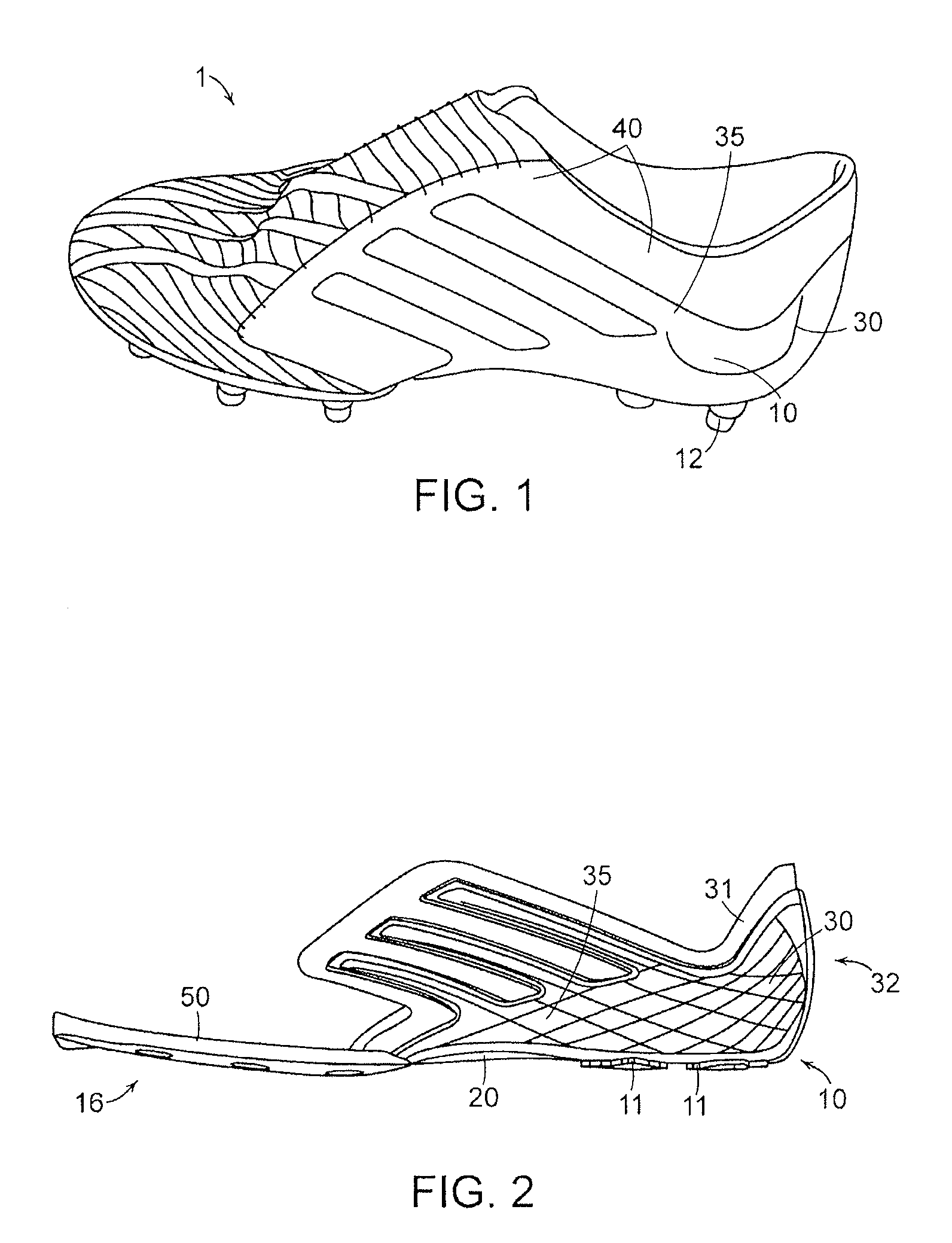
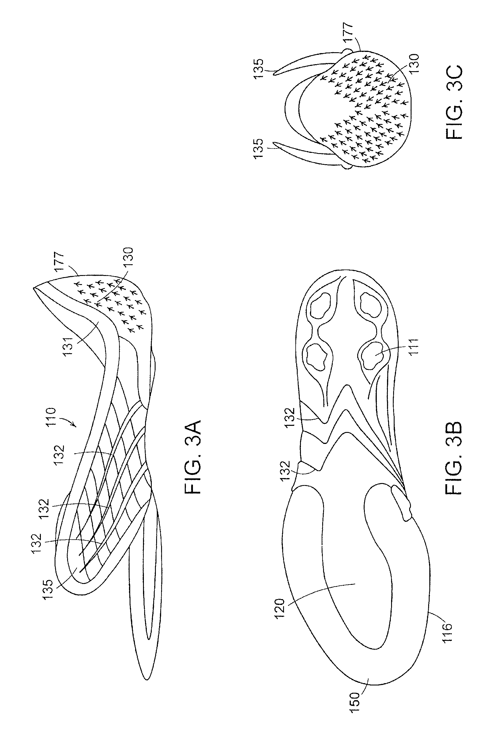
[0028]FIGS. 1 and 2 depict one embodiment of a shoe 1 (FIG. 1) and a sole element 10 (FIG. 2) for use in the shoe 1. As shown, the sole element 10 is provided as a one-piece component. Starting from a sole area 20 that extends along a region corresponding to an area below a wearer's foot, the sole element 10 includes a heel cup 30 configured to encompass a heel of the wearer's foot. In contrast to known designs, this heel cup 30, however, is not fully integrated into the upper 40 of the shoe 1. ...


PUM

PropertyMeasurementUnit
widthaaaaaaaaaa
lengthaaaaaaaaaa
areaaaaaaaaaaa

Abstract

The invention relates to a shoe having a sole element. The sole element includes a sole area extending below a wearer's foot and a heel cup three-dimensionally encompassing a heel of the wearer's foot. The heel cup alone forms at least a portion of a sidewall of the shoe.

Description

CROSS-REFERENCE TO RELATED APPLICATION[0001]This application claims priority to and the benefit of, German Patent Application Serial No. 10 2006 015 649, filed on Apr. 4, 2006, the entire disclosure of which is hereby incorporated by reference herein.TECHNICAL FIELD[0002]The present invention relates to a shoe sole, and more particularly a sole element for a shoe sole.BACKGROUND OF THE INVENTION[0003]Shoes need to meet a plurality of technical requirements, such as effectively cushioning ground reaction forces acting on the body, supporting a correct step cycle, and correcting mis-orientations, if necessary. At the same time the shoe, in particular a sports shoe, should be as lightweight as possible, since the energy needed for a course of motion of the shoe is a function of the weight of the shoe. Thus, it is an object of the development of modern sports shoes to meet the described biomechanical requirements and to produce a long-lasting shoe with the lowest possible weight.[0004]I...

Claims


Application Information

Patent Timeline
Patent Type & Authority Patents(United States)
IPC IPC(8): A43B23/08A43B13/14A43B13/18
CPCA43B1/0009A43B1/0072A43B5/02A43B13/188A43B5/06A43B13/186A43B5/025A43B23/08
Inventor ANTONELLI, BRUNO JEANSCHOLZ, WOLFGANGWEIDL, JURGENGORDON, JOSH ROBERTHILL, JANMANZ, GERD RAINER
Owner ADIDAS
Why Eureka
Try Eureka