
High-frequency digital A/V cable

a digital a/v cable and high-frequency technology, applied in the field of flat cables, can solve the problems of interference with surrounding electronic devices, transmission instability, and the insulation layer surrounding the metal core wire of high-frequency signal lines, and achieve the effect of enhancing emi protection and enhancing emi protection

Inactive Publication Date: 2011-06-07
SURE FIRE ELECTRICAL
View PDF3 Cites 26 Cited by
  • Summary
  • Abstract
  • Description
  • Claims
  • Application Information

AI Technical Summary

Benefits of technology

[0009]The present invention has been accomplished under the circumstances in view. It is the main object of the present invention to provide a high-frequency digital A / V cable, which provides enhanced EMI protection.
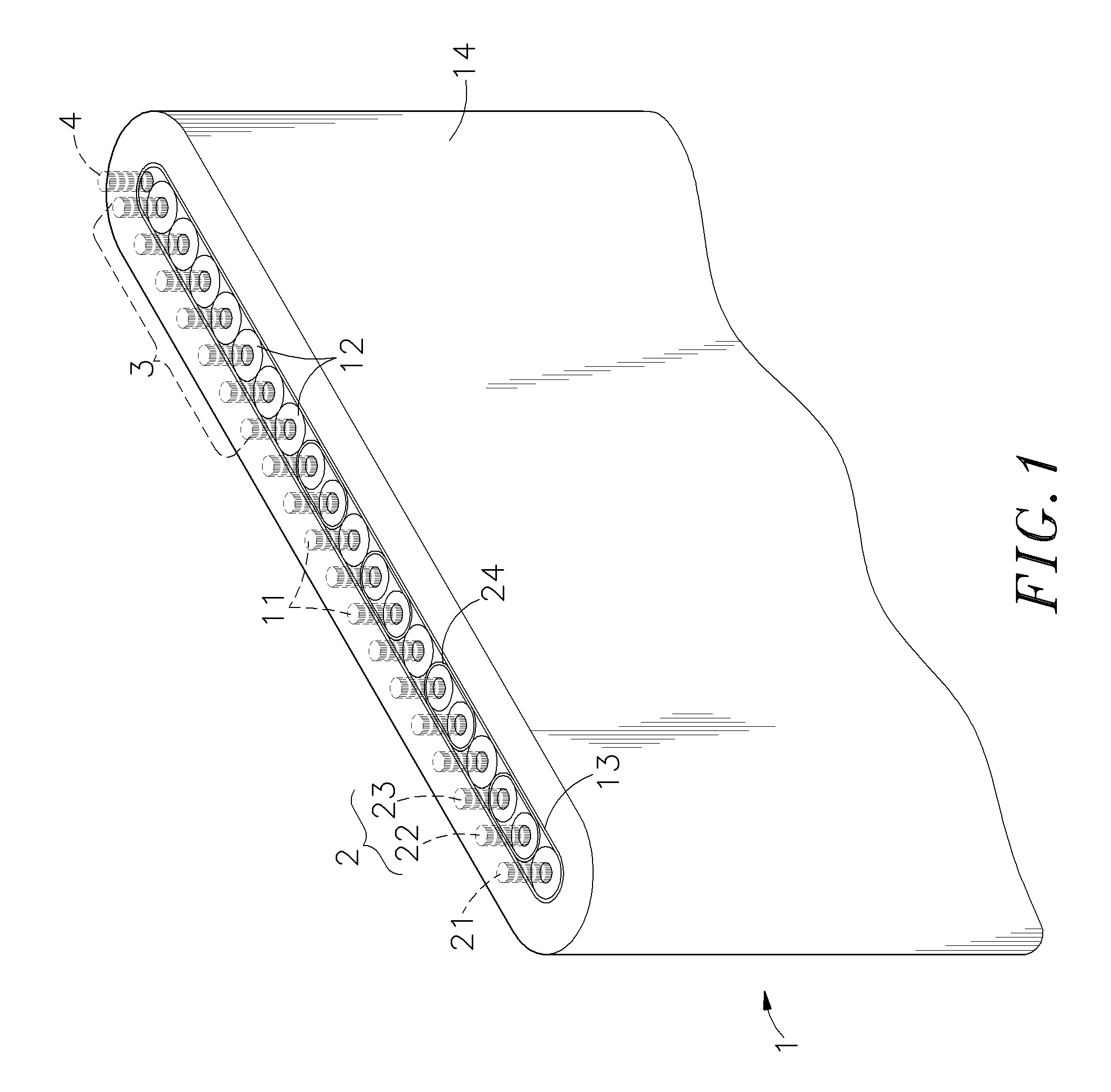
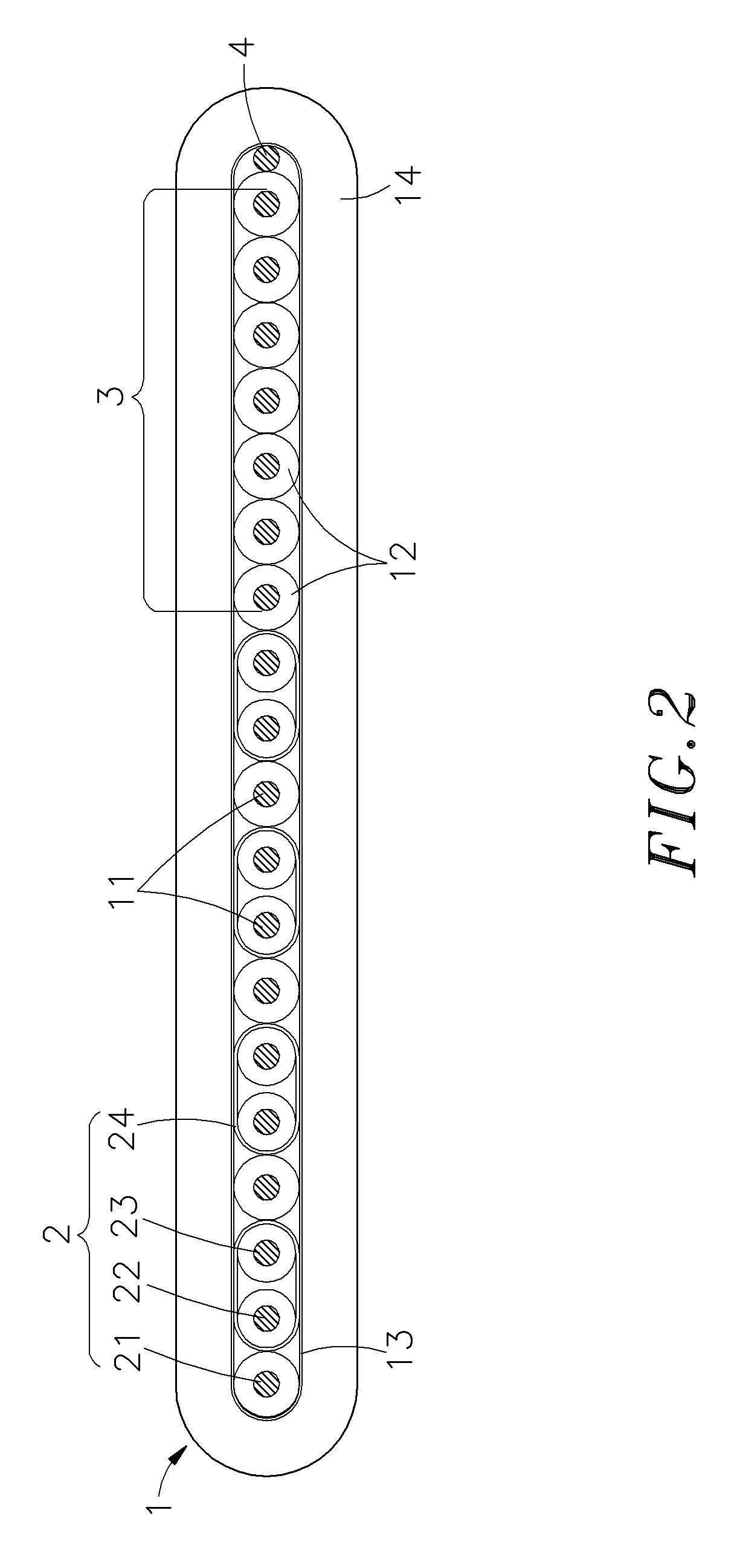
[0010]To achieve this and other objects of the present invention, the high-frequency digital A / V cable comprises a plurality of high-frequency signal line sets and a plurality of low-frequency signal lines arranged in a parallel array, an isolation layer surrounding the high-frequency signal line sets and the low-frequency signal lines, and an outer plastic sheath surrounding the isolation layer. Each high-frequency signal line set comprises a high-frequency grounding line, a first high-frequency signal line and a second high-frequency signal line. Further, a metal ground wire is arranged within the outer plastic sheath at one lateral side of the parallel array of the high-frequency signal line sets and low-frequency signal lines in a parallel manner. Further, metal shielding layers are set within the isolation layer to surround the first high-frequency signal line and second high-frequency signal line of each of the high-frequency signal line sets, providing enhanced EMI protection.

Problems solved by technology

During signal transmission, transmission interference may occur between the high-frequency signal lines and the low-frequency signal lines, resulting in transmission instability and interference with surrounding electronic devices.
1. The internal grounding wire can simply transfer noises from the signals to the earth, they cannot eliminate electromagnetic interference.
2. The insulation layers that surround the metal core wires of the high-frequency signal lines and low-frequency signal lines cannot protect the respective metal core wires against interference of external noises.

Method used


Image

  • High-frequency digital A/V cable
  • High-frequency digital A/V cable
  • High-frequency digital A/V cable

Examples


Embodiment Construction

[0018]Referring to FIGS. 1 and 2, a high-frequency digital A / V cable 1 in accordance with the present invention is shown comprising a plurality of metal core wires 11 arranged in a parallel array, an isolation layer 13 surrounding the metal core wires 11, and an outer plastic sheath 14 surrounding the isolation layer 13. The high-frequency digital A / V cable 1 shows the shape of a flat cable. One last metal core wire 11 of the parallel array of metal core wires 11 is designated as a ground wire 4. The high-frequency digital A / V cable 1 further comprises a plurality of insulation layers 12 respectively surrounding the other metal core wires 11 within the isolation layer 13. The metal core wires 11 that are respectively covered with a respective insulation layer 12 are defined to form a plurality of high-frequency signal line sets 2 and a plurality of low-frequency signal lines 3. The low-frequency signal lines 3 are arranged in parallel between the high-frequency signal line sets 2 an...


PUM

PropertyMeasurementUnit
frequencyaaaaaaaaaa
low-frequencyaaaaaaaaaa
flexibleaaaaaaaaaa

Abstract

In high-frequency digital A / V cable having high-frequency signal line sets and low-frequency signal lines arranged in a parallel array, a metal shielding layer is set within an isolation layer inside the outer plastic sheath to surround the two high-frequency signal lines of each high-frequency signal line set for EMI protection, and a metal ground wire is arranged within the outer plastic sheath at one lateral side of the parallel array of the high-frequency signal line sets and low-frequency signal lines in a parallel manner.

Description

BACKGROUND OF THE INVENTION[0001]1. Field of the Invention[0002]The present invention relates to flat cables for high-frequency signal transmission applications and more particularly, to a high-frequency digital A / V cable, which provides enhanced EMI protection.[0003]2. Description of the Related Art[0004]In recent years, audio and video application designs have been well developed. Nowadays, many audio and video products, such as VCD, DVD, digital versatile disc, high-definition digital TV, videophone, video conference system and the like are now intensively used in our daily life. When compared to conventional techniques, these new system architectures utilize digital technology to process voice and image data. Subject to different requirements for application in different fields, different standards are established, modified and updated to improve digital signal transmission (without compression) in speed and quality so that people can enjoy better quality audio and video quality...

Claims


Application Information

Patent Timeline
Patent Type & Authority Patents(United States)
IPC IPC(8): H01B7/08
CPCH01B11/00
Inventor WANG, CHANG-PIN
Owner SURE FIRE ELECTRICAL
Learn More