Display device with cooperating groove and insert sealing structure and manufacturing method therefor

a technology of sealing structure and display device, which is applied in the manufacture of electric discharge tube/lamp, discharge tube luminescnet screen, instruments, etc., can solve the problems of difficult to prevent the entry of moisture and oxygen from the outside of the display device, and achieve the effect of preventing the diffusion of moisture remaining and high long-term reliability

Inactive Publication Date: 2011-06-07
JOLED INC
View PDF6 Cites 14 Cited by
  • Summary
  • Abstract
  • Description
  • Claims
  • Application Information

AI Technical Summary

Benefits of technology

[0010]In the existing art configuration that the separation groove B is formed through the thickness of the organic insulating film 12 formed over the support substrate 10, the deterioration of the organic EL elements due to the diffusion of the moisture remaining in the display device can be prevented as mentioned above. However, the sealability by the seal resin layer 20 is insufficient, so that it is difficult to prevent the entry of moisture and oxygen from the outside of a panel and to thereby reliably prevent the deterioration of the organic EL elements.
[0011]There is a need for providing a display device which can prevent the diffusion of moisture remaining in the display device and can also prevent the entry of moisture and oxygen from the outside of the panel.
[0013]With this configuration, the seal resin layer in the peripheral region is interposed between the inner wall of the separation groove and the projection inserted in the separation groove, so that the sealability can be improved to thereby reliably prevent the entry of moisture and oxygen from the outside of the panel. Furthermore, since the separation groove is formed through the thickness of the organic insulating film, it is possible to prevent that the moisture remaining in the outer portion of the organic insulating film outside of the separation groove may pass through the organic insulating film to enter the inner portion of the organic insulating film inside of the separation groove. Accordingly, the diffusion of the moisture remaining in the display device can be prevented.
[0016]Thus, according to the present embodiments, it is possible to prevent the diffusion of moisture remaining in the display device and also reliably prevent the entry of moisture and oxygen from the outside of the panel, thereby realizing a high long-term reliability.

Problems solved by technology

However, the sealability by the seal resin layer 20 is insufficient, so that it is difficult to prevent the entry of moisture and oxygen from the outside of a panel and to thereby reliably prevent the deterioration of the organic EL elements.

Method used


Image

  • Display device with cooperating groove and insert sealing structure and manufacturing method therefor
  • Display device with cooperating groove and insert sealing structure and manufacturing method therefor
  • Display device with cooperating groove and insert sealing structure and manufacturing method therefor

Examples


first preferred embodiment

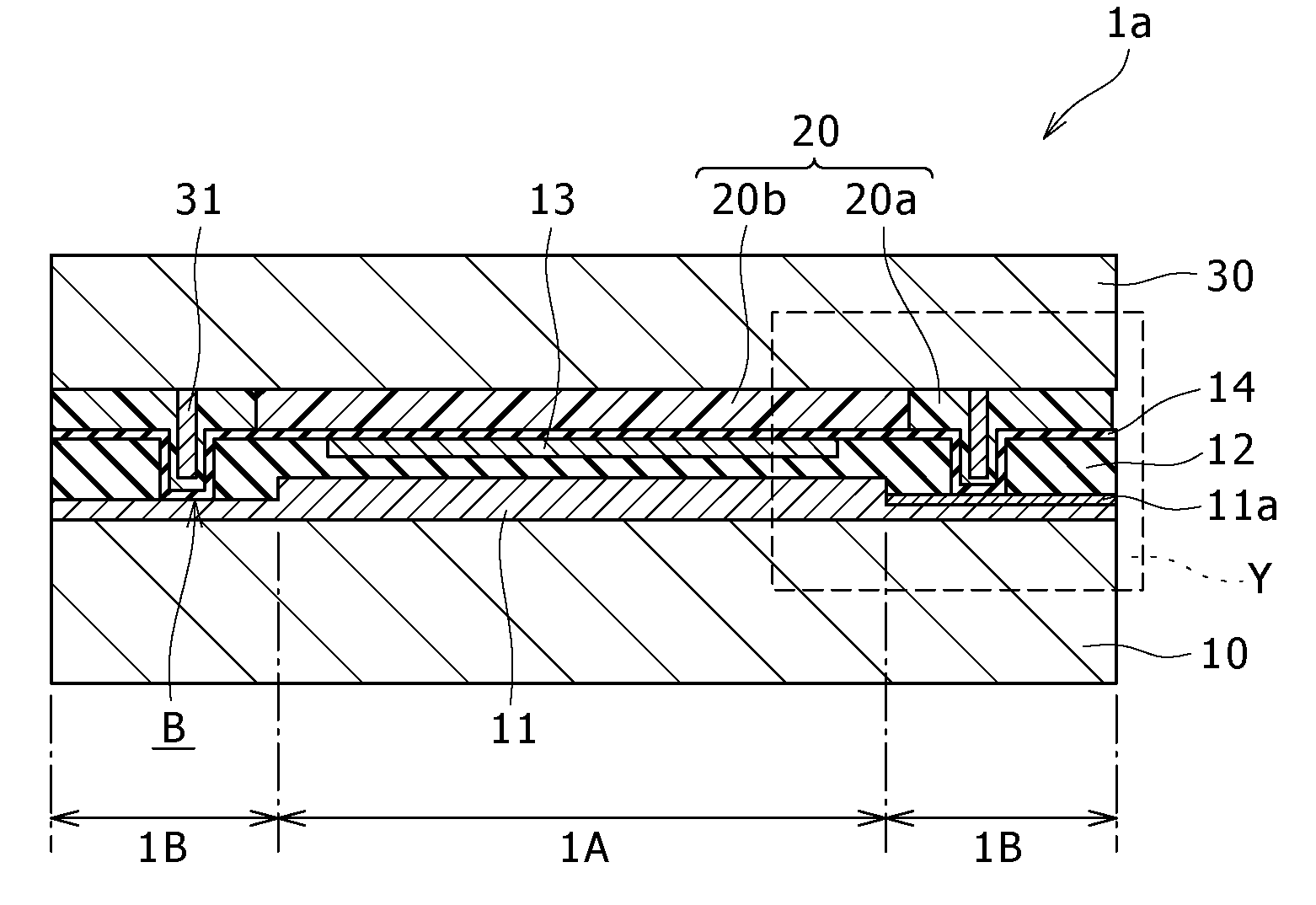
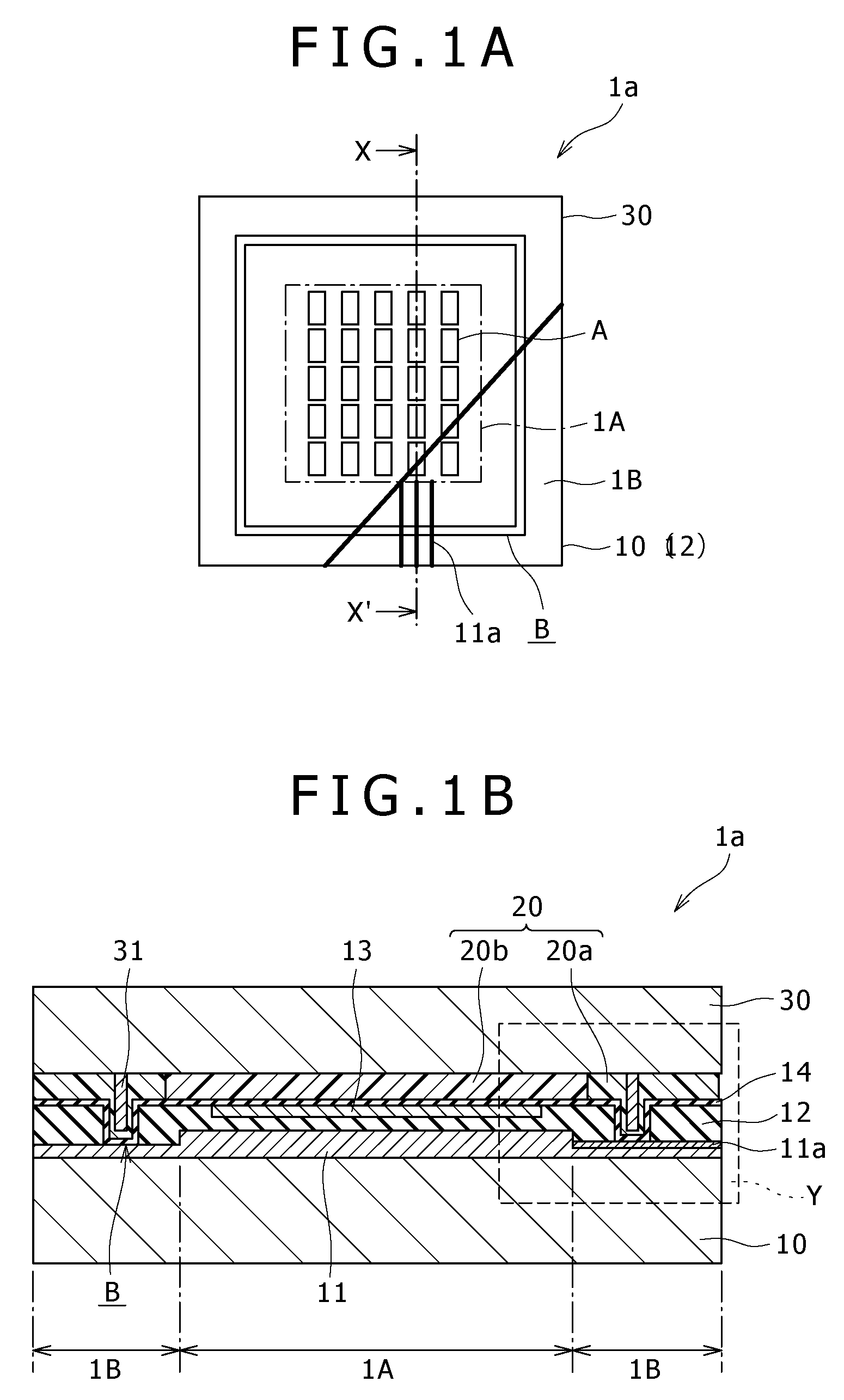
[0027]FIG. 1A is a plan view of a display device 1a according to a first preferred embodiment of the present invention, and FIG. 1B is a schematic cross section taken along the line X-X′ in FIG. 1A. In FIG. 1A, the components of the display device 1a are partially cut away for the purpose of illustration.

[0028]As shown in FIG. 1A, the display device 1a is an organic EL display using a plurality of organic EL elements A as light emitting elements. The display device 1a includes a support substrate 10 formed from a glass substrate or any other transparent substrates, a display region 1A formed above the support substrate 10 and including the organic EL elements A arranged in rows and columns, and a peripheral region 1B formed above the support substrate 10 so as to surround the display region 1A.

[0029]The display region 1A includes the organic EL elements A respectively formed at the pixels arranged in rows and columns above the support substrate 10. The display device 1a is of an act...

second preferred embodiment

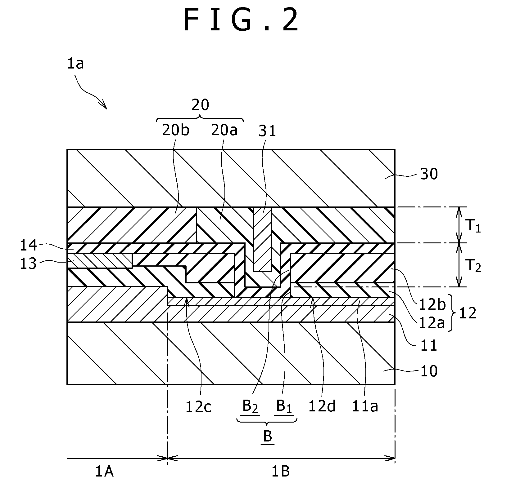
[0071]FIG. 5 is an enlarged sectional view of an essential part of a display device 1b according to a second preferred embodiment of the present invention. FIG. 5 is a view similar to FIG. 2 showing the region Y in FIG. 1B. The display device 1b according to the second preferred embodiment is different from the display device 1a according to the first preferred embodiment in the points that a plurality of separation grooves B′ are formed through the organic insulating film 12 and that a plurality of projections 31′ respectively corresponding to these separation grooves B′ are formed on the opposed substrate 30. The other configuration is similar to that of the first preferred embodiment.

[0072]More specifically, the plural separation grooves B′ are provided by two separation grooves Ba′ and Bb′ formed so as to surround the display region 1A in such a manner that the separation groove Bb′ is formed outside of the separation groove Ba′. Further, the plural projections 31′ are provided ...

third preferred embodiment

[0075]FIG. 6 is an enlarged sectional view of an essential part of a display device 1c according to a third preferred embodiment of the present invention. FIG. 6 is a view similar to FIG. 2 showing the region Y in FIG. 1B. The display device 1c according to the third preferred embodiment is different from the display device 1b according to the second preferred embodiment in the point that a plurality of additional projections 32 lower in height than the projections 31′ are formed on the opposed substrate 30 at the positions outside and inside of the projections 31′. The other configuration is similar to that of the second preferred embodiment.

[0076]More specifically, the plural projections 32 are provided by two projections 32a and 32b formed respectively inside and outside of the projections 31a′ and 31b. These projections 32a and 32b are lower in height than the projections 31a′ and 31b′ and are opposed to the organic insulating film 12 in the peripheral region 1B. Thus, the proje...


PUM


Abstract

A display device includes: a support substrate including a display region where a plurality of display elements are arranged and a peripheral region where a drive circuit for each display element is provided in the periphery of the display region; a seal resin layer formed in at least the peripheral region; an opposed substrate bonded through the seal resin layer to the support substrate, sealing the display elements; an organic insulating film formed on the support substrate so as to insulate the drive circuit; a separation groove formed through the thickness of the organic insulating film so as to surround the display region and separate the organic insulating film into an inner portion and an outer portion; and a framelike projection formed on the opposed substrate so as to be opposed to the separation groove.

Description

CROSS REFERENCES TO RELATED APPLICATIONS[0001]The present invention contains subject matter related to Japanese Patent Application JP 2007-104420 filed with the Japan Patent Office on Apr. 12, 2007, the entire contents of which being incorporated herein by reference.BACKGROUND OF THE INVENTION[0002]1. Field of the Invention[0003]The present invention relates to a display device and a manufacturing method therefor, and more particularly to a display device having organic EL (electro Luminescent) elements and a manufacturing method for the display device.[0004]2. Description of the Related Art[0005]In recent years, a next-generation display has been actively developed in the field of a display device, wherein space saving, high luminance, low power consumption, etc. are demanded. As such a display device, an organic EL display using organic EL elements has now received attention. Such an organic EL display is of a self-luminous type, so that the viewing angle is wide and no backlight ...

Claims


Application Information

Patent Timeline
Patent Type & Authority Patents(United States)
IPC IPC(8): H01J17/00H05B33/00H01S3/08
CPCH01L51/5237H10K59/871H10K59/873H10K59/8722G02F1/1339H10K50/844H10K50/841
Inventor NAKADAIRA, TADAKATSU
Owner JOLED INC
Why Eureka
Try Eureka