Motor drive control device and image forming apparatus

a control device and motor technology, applied in the direction of electric controllers, ignition automatic control, instruments, etc., can solve the problems of unstable rotational speed control with respect to the photoconductive drum, difficult to realize accurate rotational speed control, and difficult to accurately control the rotational speed of the motor. achieve the effect of stable speed control signal

Inactive Publication Date: 2011-06-07
KYOCERA DOCUMENT SOLUTIONS INC
View PDF2 Cites 4 Cited by
  • Summary
  • Abstract
  • Description
  • Claims
  • Application Information

AI Technical Summary

Benefits of technology

[0007]An object of the present invention is to solve the problem described above and realize a motor drive control capable of stably rotating a driven member by making the oscillation at a time of executing a feedback control be unlikely to occur and making it possible to generate a stable speed control signal.

Problems solved by technology

Therefore, it is difficult to accurately control a rotational speed of the motor to be a target speed.
Accordingly, it is difficult to cancel those elements from the output by filtering and use the same, and a rotational speed control with respect to the photoconductive drum becomes unstable.
Therefore, it is difficult to realize an accurate rotational speed control with the motor rotational speed control by merely feeding back the motor rotational speed and the drum rotational speed.
However, if the speed control signal is generated by the two-step correction in accordance with the feedbacks of the drum rotational speed and the motor rotational speed, oscillation is likely to occur, and the generated speed control signal is not stable, so that it is difficult to perform a rotational drive control with respect to the photoconductive drum stably.

Method used


Image

  • Motor drive control device and image forming apparatus
  • Motor drive control device and image forming apparatus
  • Motor drive control device and image forming apparatus

Examples


Embodiment Construction

[0015]Hereinafter, a motor drive control device and an image forming apparatus in accordance with an embodiment of the present invention will be described with reference to the drawings.

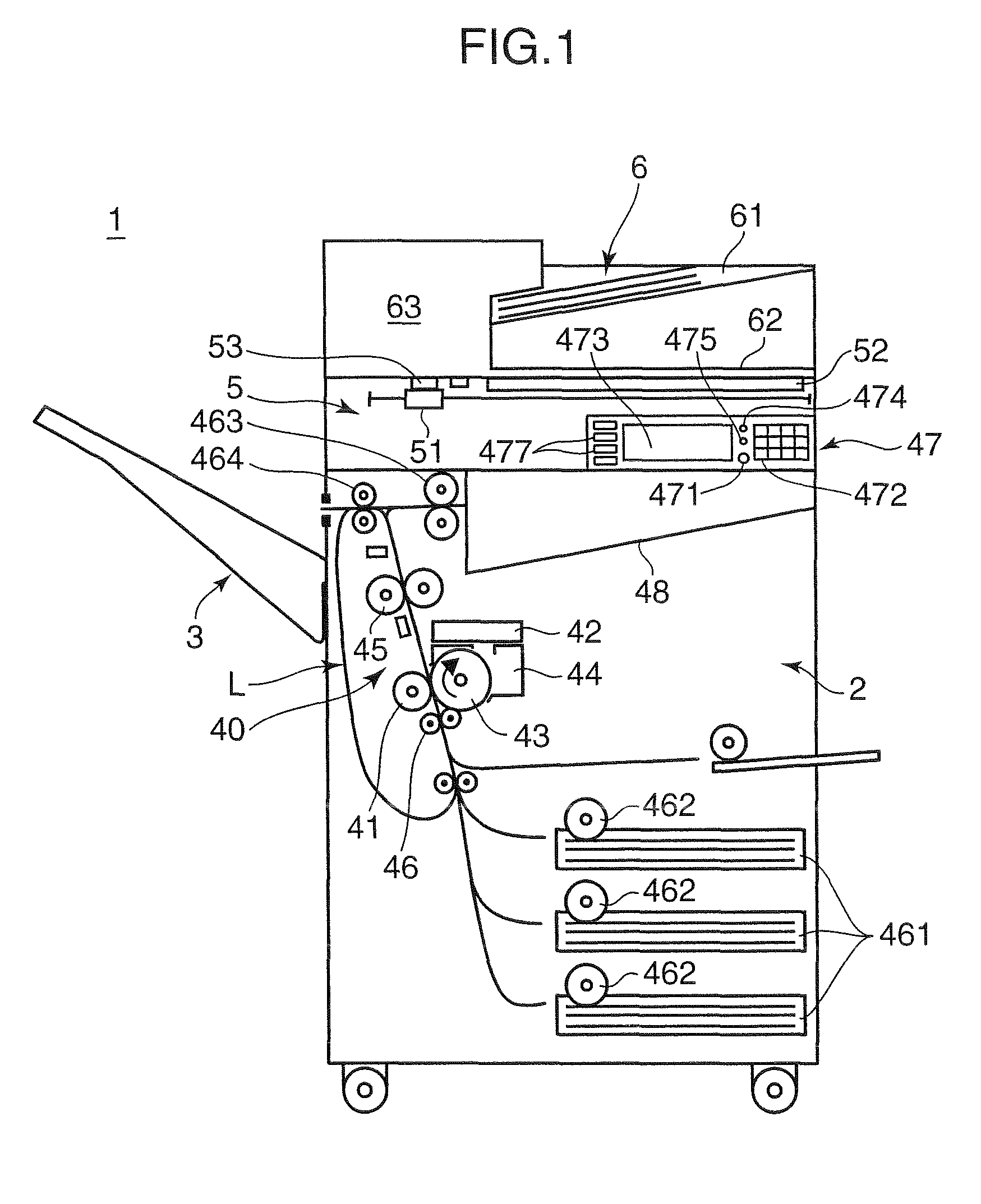
[0016]FIG. 1 is a side view schematically showing an internal configuration of a complex machine which is an example of an image forming apparatus in accordance with an embodiment of the present invention. The complex machine 1 has functions such as a copying function, a printer function, a scanner function, and a facsimile function. This complex machine 1 includes main body 2, a stack tray 3 provided on a left side of the main body 2, a document reading section 5 provided in an upper portion of the main body 2, and a document feeding section 6 provided on top of the document reading section 5.

[0017]Further, an operating section 47 is provided on a front portion of the complex machine 1. The operating section 47 includes a start key 471 for allowing a user to input a print executing instruction, nume...


PUM


Abstract

A motor drive control device for controlling a rotational speed of a motor includes: a motor driver for rotationally driving a motor; a correction amount calculating section for detecting a rotational speed of an output of the motor in accordance with an alternate current signal outputted from an FG sensor and detecting a rotational position of a photoconductive drum, which is rotated by a rotational drive force of the motor, in accordance with a pulse outputted from an encoder; a speed controller for generating a speed control signal corresponding to a total correction amount, which is a sum of a correction amount calculated in the correction amount calculating section based on a rotational speed of the motor and a correction amount calculated based on a rotational position of the photoconductive drum, and outputting the generated speed control signal to the motor driver.

Description

BACKGROUND OF THE INVENTION[0001]1. Field of the Invention[0002]The present invention relates to a motor drive control device and an image forming apparatus. More particularly, it relates to a control of rotationally driving a driven member in a predetermined state.[0003]2. Description of the Related Art[0004]Conventionally, in image forming apparatuses such as a copying machine and a printer, a high accuracy has been requested in a speed of a traction motor used for rotationally driving a photoconductive drum. Accordingly, a drum rotational speed outputted from an encoder mounted to a driving shaft of the photoconductive drum and a motor rotational speed outputted from an encoder mounted to an output shaft of a motor as a drive power source of the photoconductive drum are fed back, so that a speed control with respect to a traction motor is performed. Such rotational driving device has been proposed in, for example, Japanese Patent Unexamined Publication No. 2003-18880 (patent docu...

Claims


Application Information

Patent Timeline
Patent Type & Authority Patents(United States)
IPC IPC(8): G05B11/42G03G15/00G03G21/14G03G21/16H02P29/00
CPCG03G15/5008
Inventor RYU, GUNMUN
Owner KYOCERA DOCUMENT SOLUTIONS INC
Why Eureka
Try Eureka