Variable hydraulic system, pump output flow control method, construction machinery

A hydraulic system and variable technology, applied in the field of construction machinery and variable hydraulic systems, can solve problems such as high requirements for machining accuracy and system cleanliness, high probability of component failure, and complex main valve structure, achieving high maintainability and repairability. , the effect of low failure probability and simple structure

Active Publication Date: 2020-07-28
GUANGXI LIUGONG MASCH CO LTD
View PDF7 Cites 0 Cited by
  • Summary
  • Abstract
  • Description
  • Claims
  • Application Information

AI Technical Summary

Problems solved by technology

However, there is always a pressure loss ΔP in the load-sensing control system. When the operation is that the system flow increases, it will cause a lot of power loss, and when the load pressure of each actuator in the compound operation is very different, because the pump flow is only affected by the highest load Pressure control, the output flow of the main pump will be more than the sum of the demand flow of the actuators, which will also cause power loss
The main valve structure of the load-sensing control system is complex and requires high machining accuracy and system cleanliness, so the probability of component failure is relatively high

Method used


Image

  • Variable hydraulic system, pump output flow control method, construction machinery

Examples


Embodiment Construction

[0025] The specific implementation will be described below in conjunction with the accompanying drawings.

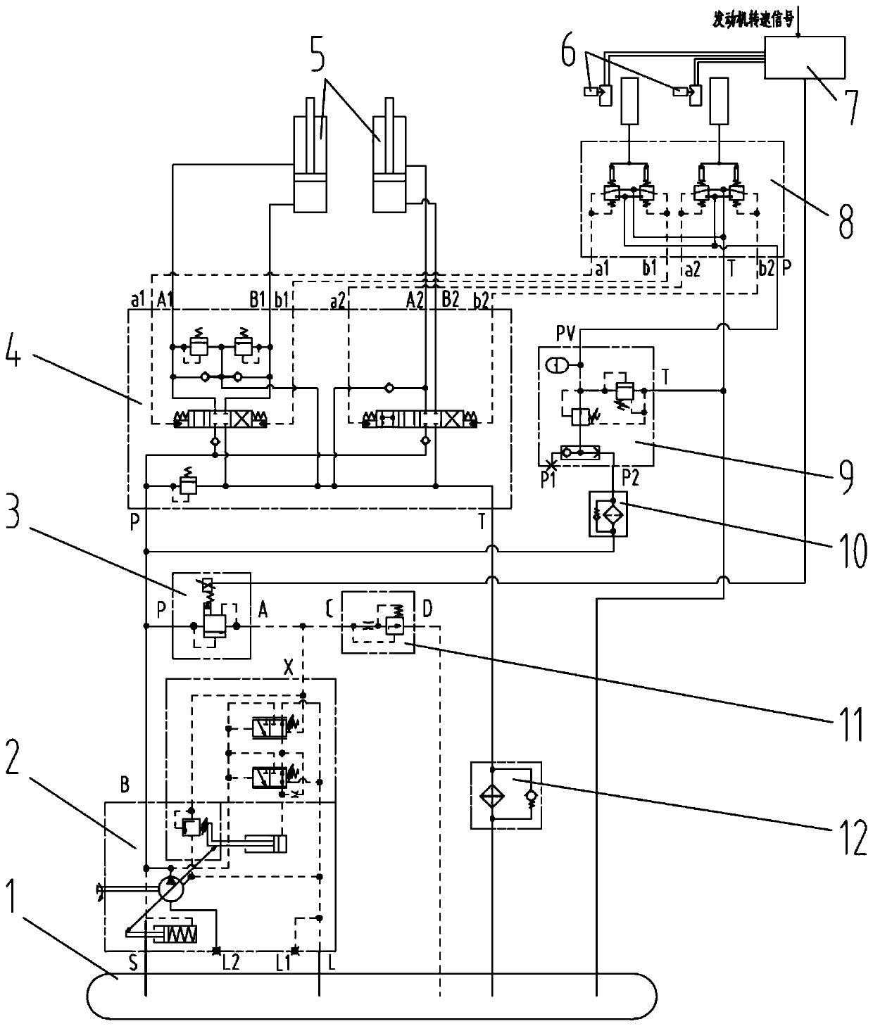
[0026] As shown in the drawings, the variable hydraulic system of the present invention consists of a hydraulic oil tank 1, a hydraulically controlled plunger pump 2, an electric proportional pressure reducing valve 3, a multi-way reversing valve 4, an oil cylinder 5, an angle sensor 6, a controller 7, and a pilot valve 8. Pilot oil supply valve 9, pilot oil filter 10, speed control valve 11, radiator 12 and other components. The S port of the hydraulic control plunger pump 2, that is, the oil inlet, is connected to the hydraulic oil tank 1, the B port of the hydraulic control plunger pump 2 is connected to the P port of the electric proportional pressure reducing valve 3, the P port of the multi-way reversing valve 4, The oil inlet port of the pilot oil filter 10 is connected, the S port of the hydraulic control plunger pump 2 is the oil inlet port, the B oil port is th...


PUM


Abstract

The invention relates to a variable delivery hydraulic system. The variable delivery hydraulic system comprises a hydraulic oil tank, a liquid control plunger pump, a hydraulic execution piece, a quantitative reversing valve, a reversing valve control device, an electric proportional pressure reducing valve, and a controller. The liquid control plunger pump sucks hydraulic oil from the hydraulic tank and is driven by an engine, the quantitative reversing valve is connected to the hydraulic execution valve and is used for controlling the hydraulic execution piece, the quantitative reversing valve control device is used for controlling the action of a direction reversing valve. A port B of the liquid control plunger pump is simultaneously connected with port P of the direction switching valve and port P of the electric proportional pressure reducing valve, a port A of the electric proportional pressure reducing valve is connected with the hydraulic oil tank through a speed adjusting valve, the port A of the electric proportional pressure reducing valve is connected with a port X of the liquid control plunger pump, the electrically controlled end of the electric proportional pressurereducing valve is connected with the controller, and the controller outputs corresponded electric signals according to the movement range of the reversing valve control device and the rotating speed of the engine after detecting the movement range of the reversing valve control device through a sensing device and obtaining a rotation parameter of the engine so as to enable the electric proportional pressure reducing valve to generate a corresponding pressure difference value. The variable hydraulic system has the advantages that the performance is stable and excellent, the cost low, and the energy-saving effect is good.

Description

technical field [0001] The invention relates to a hydraulic system, more specifically, to a variable hydraulic system, a pump output flow control method, and engineering machinery. Background technique [0002] At present, common variable hydraulic systems include positive flow control systems, negative flow control systems, and load-sensing control systems. Each variable hydraulic system has its own advantages and disadvantages. It is difficult to distinguish which is good and which is bad. Only by choosing the appropriate hydraulic system for different operating conditions can the advantages of the hydraulic system be fully utilized to achieve energy saving, high efficiency and comfort. [0003] The positive flow control system belongs to the pilot sensor control system, which uses the pilot control load pressure of the multi-way reversing valve as the control signal to control the output flow of the variable pump, the flow of the main pump and the oil intake of the actuat...

Claims


Application Information

Patent Timeline
Patent Type & Authority Patents(China)
IPC IPC(8): F15B11/16F15B13/06F15B13/16
CPCF15B11/16F15B13/06F15B13/16
Inventor 莫雄超梁振国王允范武德
Owner GUANGXI LIUGONG MASCH CO LTD
Why Eureka
Try Eureka