Power-measured pulses for thermal trimming

a technology of resistors and pulses, applied in the direction of resistor details, resistor mounting/supporting, resistors with plural resistive elements, etc., can solve the problems of unpredictable instability of resistors, inability to ensure that the temperature induced by subsequent pulses will have a specific relationship, and the instability of resistors can become unstable during trimming signals, etc., to achieve constant power dissipation and unpredictable instability

Inactive Publication Date: 2011-06-07
SENSORTECHNICS
View PDF7 Cites 0 Cited by
  • Summary
  • Abstract
  • Description
  • Claims
  • Application Information

AI Technical Summary

Benefits of technology

[0008]In thermal trimming of thermally-isolated resistors, such as those housed in thermally-isolated microstructures, the heater-resistor can become unstable during the trimming signal. This instability leads to at least two problems specific to the context of thermal trimming, namely thermal runaway during a given pulse, and an inability to ensure that the temperature induced by a subsequent pulse will have a specific relationship to the previous pulse, such as being higher or lower by a specific amount. The instability of the resistor is unpredictable. Thus, it is advantageous that the trimming signals be “power-measured”, which allows the power (and therefore the temperature) to be known throughout (before, during, and after) a sequence of electrical signals applied to the heater. It is also advantageous in some cases that the trimming signals be “power-controlled”, such that they maintain a substantially constant power dissipation during the signal applied to the heater, even if the heater-resistance is unstable and changing its material properties.

Problems solved by technology

In thermal trimming of thermally-isolated resistors, such as those housed in thermally-isolated microstructures, the heater-resistor can become unstable during the trimming signal.
This instability leads to at least two problems specific to the context of thermal trimming, namely thermal runaway during a given pulse, and an inability to ensure that the temperature induced by a subsequent pulse will have a specific relationship to the previous pulse, such as being higher or lower by a specific amount.
The instability of the resistor is unpredictable.

Method used


Image

  • Power-measured pulses for thermal trimming
  • Power-measured pulses for thermal trimming
  • Power-measured pulses for thermal trimming

Examples


Embodiment Construction

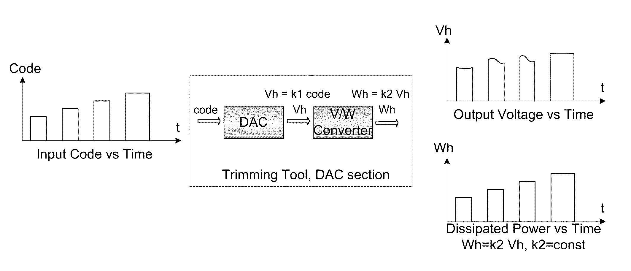
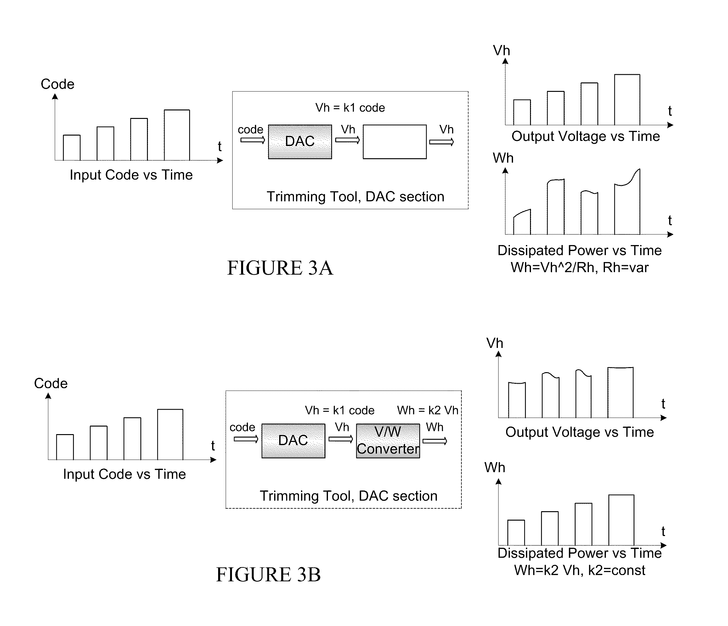
[0027]This invention proposes a method to mitigate the above-described problem of heater-resistor stability. Thermal trimming is fundamentally controlled by temperature, and typically there is no reliable temperature sensor in the trimming zone (because typically the heater-resistor and functional-resistor may be both unstable at trimming temperatures, and because design of another explicit temperature sensor would raise further inconvenience). Therefore, the resistors, microstructure, and system to apply heating pulses, are co-designed, taking account of the temperature-coefficients (magnitude and sign) of resistance of the heater, heating-pulse-voltage, pulse-current and pulse-power, speed of resistance changes in the heater-resistor during thermal trimming, relative temperature ranges of thermal trimmability of the heater-resistor and functional resistor, as well as thermal inertia and thermal isolation of the microstructure(s).

[0028]Pulses of constant electric power are used for...


PUM

PropertyMeasurementUnit
temperaturesaaaaaaaaaa
resistanceaaaaaaaaaa

Abstract

A circuit for trimming a thermally-trimmable resistor, measuring a temperature coefficient of resistance of the thermally-trimmable resistor, and annealing a thermally-trimmable resistor post-trimming, the circuit comprising: a thermally-isolated area on a substrate housing the thermally-trimmable resistor; heating circuitry for applying a signal to a heating resistor; and a constant-power module adapted to maintain power dissipated in the heating resistor substantially constant over a duration of the signal by varying at least one parameter of the signal as a result of a change in resistance of the heating resistor during the signal.

Description

CROSS-REFERENCE TO RELATED APPLICATIONS[0001]The present application claims priority of U.S. Provisional Patent Application No. 60 / 762,884, filed on Jan. 30, 2006.TECHNICAL FIELD[0002]The invention relates to resistors and resistor networks which are electro-thermally trimmable, and more specifically, to thermal trimming of these resistors to adjust parameters such as resistance, temperature coefficient of resistance and relative temperature coefficient of resistance.BACKGROUND OF THE INVENTION[0003]Prior art on thermal trimming of resistors has disclosed and addressed several configurations and variations. Thermal trimming of a thermally-mutable resistor is possible whether or not it is residing on or in a thermally-isolated microstructure. Also, there may or may not be a separate auxiliary heater used to apply heating power to a functional resistor which is intended to be trimmed. A sequence of electric voltage or current pulses is applied to a resistor (whether separate or not), ...

Claims


Application Information

Patent Timeline
Patent Type & Authority Patents(United States)
IPC IPC(8): H01C10/00
CPCH01C17/267H01L28/20Y10T29/49082Y10T29/49004
Inventor LANDSBERGER, LESLIE M.GRUDIN, OLEGFROLOV, GENNADIY
Owner SENSORTECHNICS
Why Eureka
Try Eureka