Organic light emitting diode display

a light-emitting diode and display technology, applied in the direction of electrical apparatus construction details, instruments, casings/cabinets/drawers, etc., can solve the problems of low power consumption of oled displays, high luminance, and inability to adjust the display speed, so as to improve the bezel and improve the mechanical strength and impact resistance

Inactive Publication Date: 2011-06-07
SAMSUNG DISPLAY CO LTD
View PDF18 Cites 3 Cited by
  • Summary
  • Abstract
  • Description
  • Claims
  • Application Information

AI Technical Summary

Benefits of technology

[0010]Exemplary embodiments of the present disclosure provide an OLED display having enhanced mechanical strength and impact resistance, due to an improved bezel, which is coupled to a panel assembly.
[0018]In an exemplary embodiment of the present disclosure, a plurality of grooves may be formed on a front surface and a rear surface of the bezel, to partly reduce a thickness / weight of the bezel. Alternatively, a plurality of grooves may be formed on inner and outer side surfaces of the bezel, to partly reduce a width / weight of the bezel. Alternatively, a plurality of holes may be formed in the front surface and the rear surface of the bezel. Alternatively, a plurality of holes may be formed in inner and outer side surfaces of the bezel.

Problems solved by technology

Further, OLED displays have low power consumption, high luminance, quick response, and the like.
Therefore, the mechanical strength of an OLED may be compromised.
Therefore, when a user accidentally drops an electronic device having an OLED display, relatively large torsion loads and / or relatively large bending loads are applied to the bezel, and thus, the bezel is deformed.
This may cause damage to the panel assembly.

Method used


Image

  • Organic light emitting diode display
  • Organic light emitting diode display
  • Organic light emitting diode display

Examples


Embodiment Construction

[0035]Reference will now be made in detail to the exemplary embodiments of the present invention, examples of which are illustrated in the accompanying drawings, wherein like reference numerals refer to the like elements throughout. The exemplary embodiments are described, below in order to explain the aspects of the present invention, by referring to the figures.

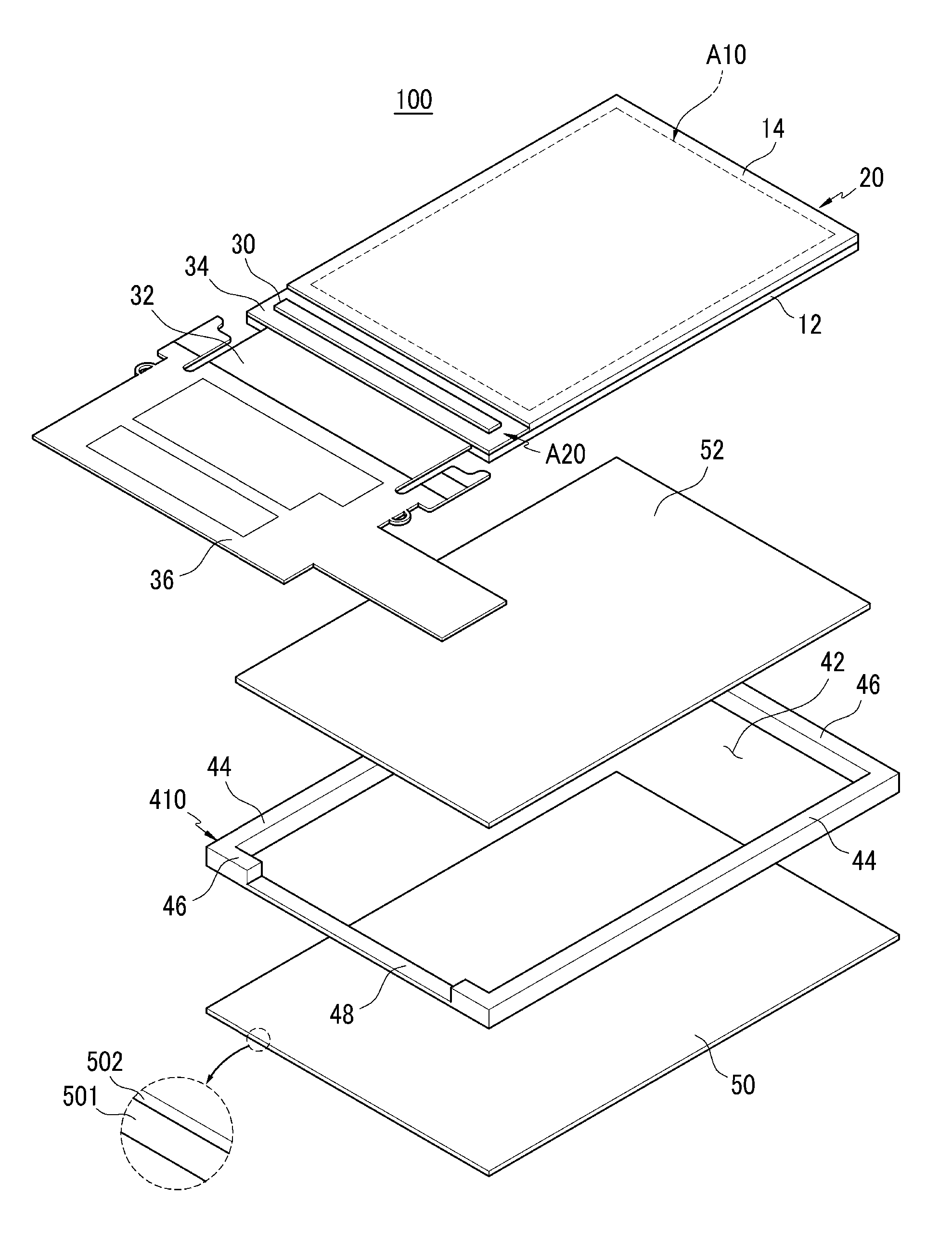
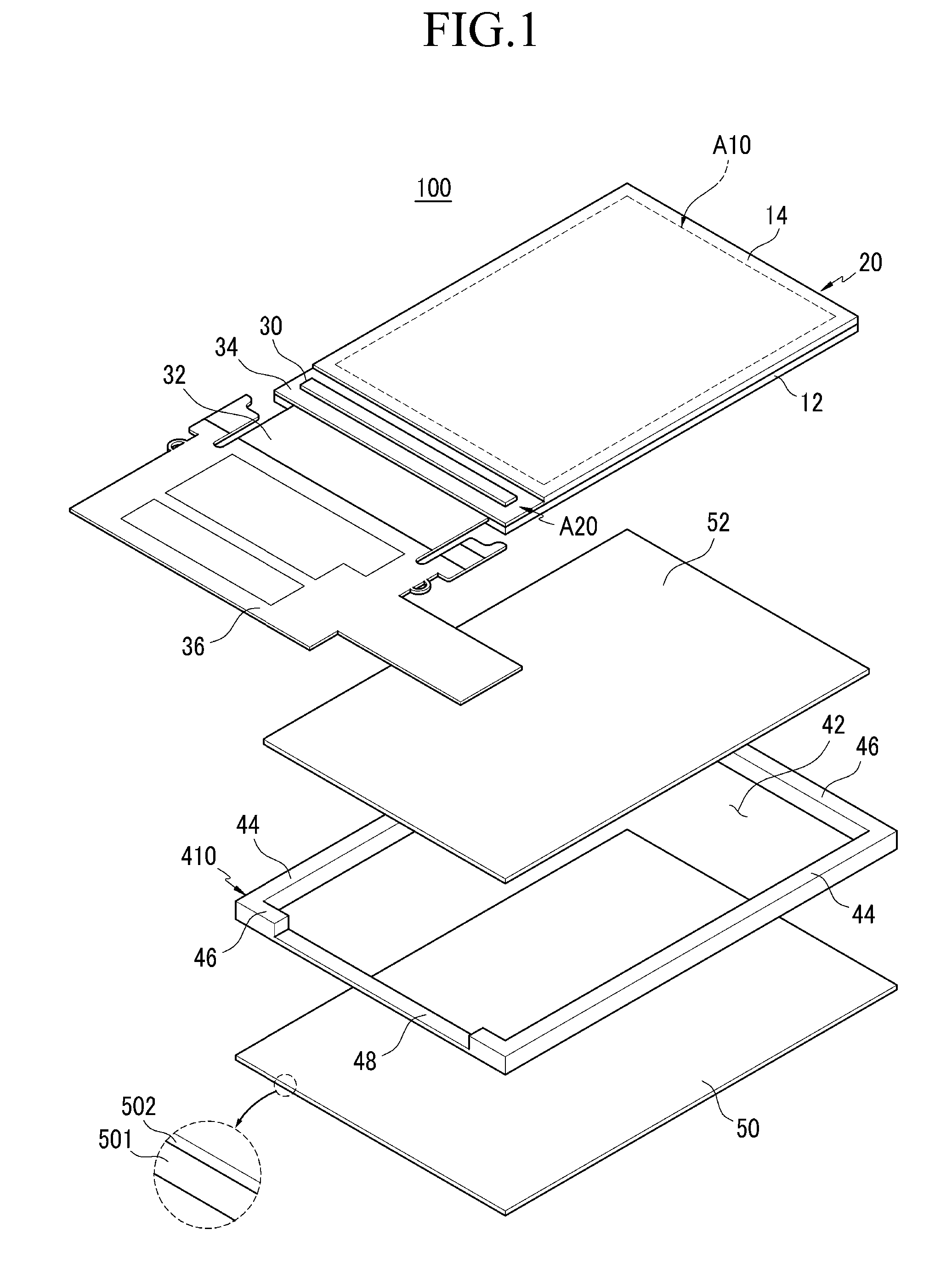
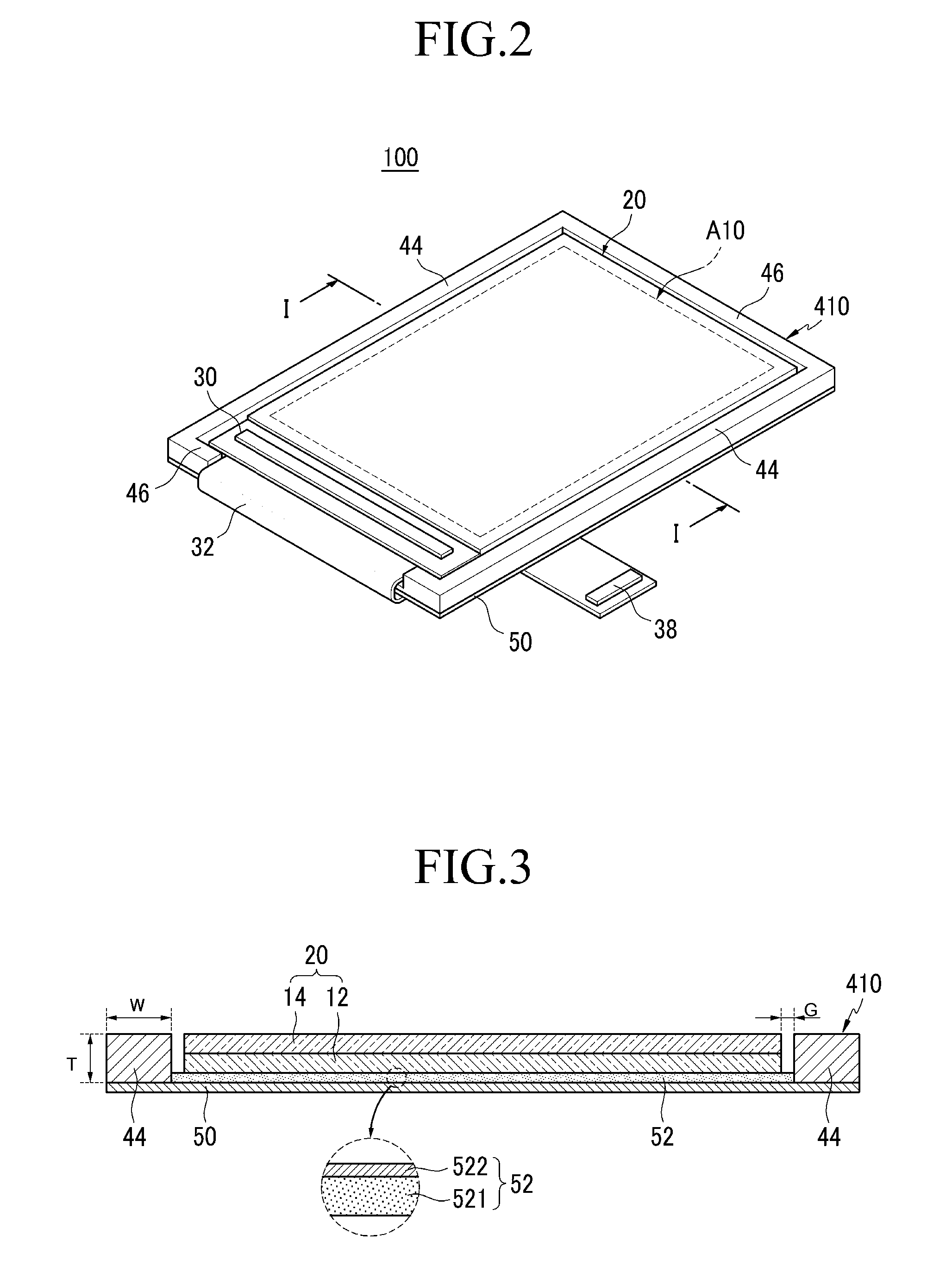
[0036]FIG. 1 is an exploded perspective view of an OLED display 100, according to a first exemplary embodiment of the present disclosure, FIG. 2 is an assembled perspective view of the OLED display 100, and FIG. 3 is a cross-sectional view taken along line I-I, of FIG. 2. Referring to FIGS. 1 to 3, the OLED display 100 includes: a panel assembly 20 having a display region A10 to display an image, and a pad region A20; a bezel 410 coupled to the panel assembly 20; and a printed circuit board (PCB) 36 electrically connected to the panel assembly 20, via a flexible printed circuit board (FPCB) 32.

[0037]The panel assembly 20 in...


PUM


Abstract

An OLED display including: a panel assembly having a display region, a pad region, and a plurality of OLEDs formed in the display region; a bezel disposed around, and spaced apart from the panel assembly; and a fixing member to fix the panel assembly to the bezel.

Description

CROSS-REFERENCE TO RELATED APPLICATIONS[0001]This application claims the benefit of Korean Application No. 2008-11138, filed Feb. 4, 2008, in the Korean Intellectual Property Office, the disclosure of which is incorporated herein by reference.BACKGROUND OF THE INVENTION[0002]1. Field of the Invention[0003]Aspects of the present disclosure relate to an organic light emitting diode (OLED) display. More particularly, aspects of the present disclosure relate to an OLED display having enhanced mechanical strength, due to an improved bezel that supports a panel assembly.[0004]2. Description of the Related Art[0005]An OLED display includes a plurality of OLEDs, each having a hole injection electrode, an organic emissive layer, and an electron injection electrode. The OLEDs emit light using energy generated when excitons, generated by electron-hole combinations in the organic light emitting layer, drop from an excitation state to a ground state.[0006]By the above principle, OLED displays ha...

Claims


Application Information

Patent Timeline
Patent Type & Authority Patents(United States)
IPC IPC(8): H05K5/00H05K7/00
CPCH01L51/0096H01L51/5237G02F2201/503Y02E10/549H10K77/10H10K59/87G02F1/133308H01L28/56H10K50/84
Inventor YEE, DONG-SUHA, KUEN-DONGLEE, HYUN-HEEMOON, CHAN-KYOUNGHWANG, HYUN-MINKIM, EUN-AH
Owner SAMSUNG DISPLAY CO LTD
Why Eureka
Try Eureka