
Blanking panel for standardized equipment rack and cabinet enclosure

a technology for equipment racks and cabinet enclosures, applied in the direction of support structure mounting, card stiffeners, show hangers, etc., can solve the problems of reducing the service life of equipment racks, and reducing the service life of equipment, so as to eliminate the discomfort of installing and dismantling, and prevent air flow. , the effect of convenient, comfortable and reliable engagement and removal

Active Publication Date: 2011-06-14
AQUILA INC
View PDF15 Cites 18 Cited by
  • Summary
  • Abstract
  • Description
  • Claims
  • Application Information

AI Technical Summary

Benefits of technology

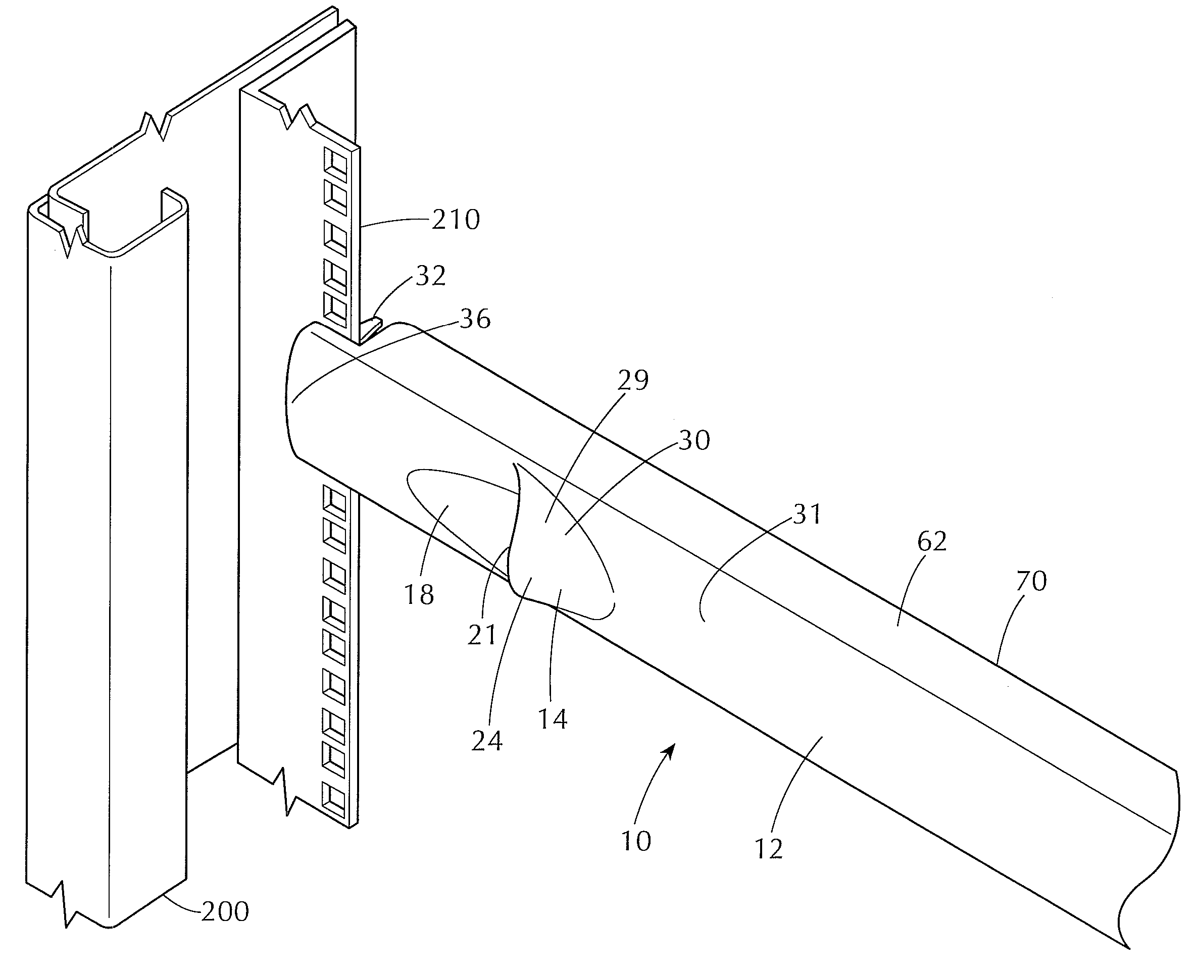
[0013]Each grip is spaced laterally inward from an associated adjacent end portion of the blanking panel at least about 5 cm to permit engagement of the grip by the user, with said first and second hands of the user located entirely between said first and second ends of the blanking panel. The laterally inward placement of the grips allows the user to mount and remove the blanking panel without physical stress or abrasion to the hands of the installer during installation and removal of large quantities of blanking panels.
[0014]The user may conveniently, comfortably and reliably engage and remove the blanking panel from the equipment rack or cabinet enclosure by grasping the first and second grips regardless of the clearance laterally outward of the ends of the blanking panel and regardless of laterally inwardly projecting rack frame or door structure. This design and mechanism eliminates the problems of discomfort in installing and removing, and of abrading or scraping hands and knuckles.
[0015]The stacking structure of the blanking panel allows multiple blanking panels to be stacked in a stable manner without the use of an external support structure, such as a box or the like.
[0016]Resiliently flexible sealing skirt members extend along the edges of the blanking panels and form a positive seal with electronic equipment or other blanking panels in mounting locations immediately above and below the blanking panel to prevent air flow therebetween. The sealing blanking panels may be mounted and removed without the need to disassemble and re-assemble adjacent blanking panels or electronic equipment.

Problems solved by technology

Such prior constructions of blanking panels generally serve their intended purposes; however, flat sheet blanking panels often warp or bend and lose sealing effectiveness in the rack, and the prior snap-mount blanking panels do not provide an effective barrier to air flow.
Further, the prior snap-mount blanking panels can be difficult and uncomfortable to engage and disengage from the rack or cabinet enclosure because inadequate room is available from the finger lifts or turn buttons to clear the edges of the rack or cabinet.
Indeed, it is not uncommon for users of prior blanking panels to abrade or scrape their hands and knuckles on the cabinet enclosure or rack when mounting or removing the panels.
Thus, the difficulty and discomfort involved in installing and replacing prior blanking panels can be significant.
The prior blanking panels do not allow for stable stacking of multiple blanking panels for storage and thus must be stored in a container, such as a corrugated box, which is undesirable for data centers and the like.
In addition, the prior blanking panels do not provide a means for reliably measuring atmospheric conditions of the ambient area which is often desirable in data centers and the like, or provide an area for mounting signage or for a writing surface which can provide information about the rack or devices therein.
Further, prior blanking panels do not provide a means to pass cable through the blanking panel.

Method used


Image

  • Blanking panel for standardized equipment rack and cabinet enclosure
  • Blanking panel for standardized equipment rack and cabinet enclosure
  • Blanking panel for standardized equipment rack and cabinet enclosure

Examples


Embodiment Construction

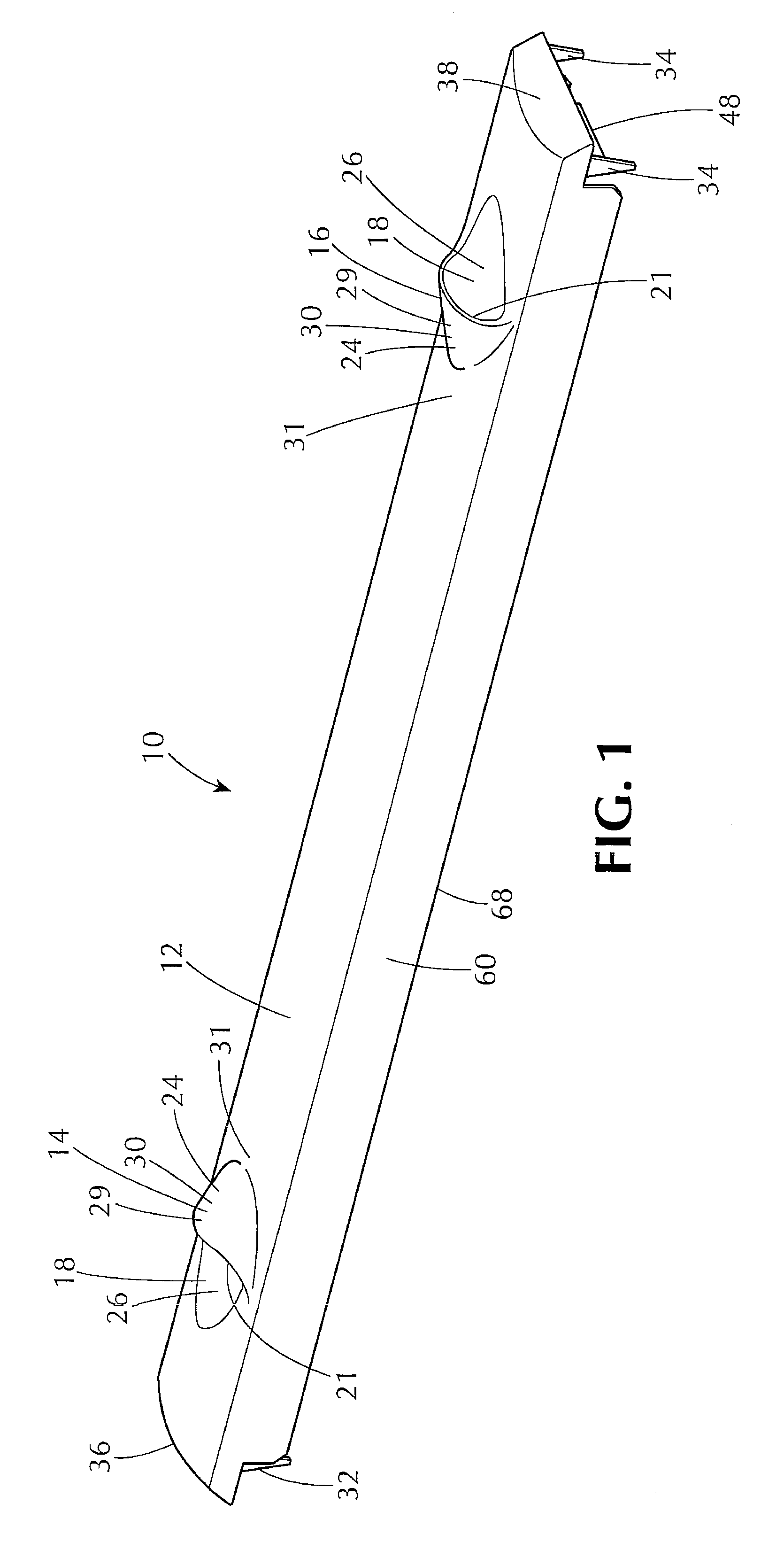
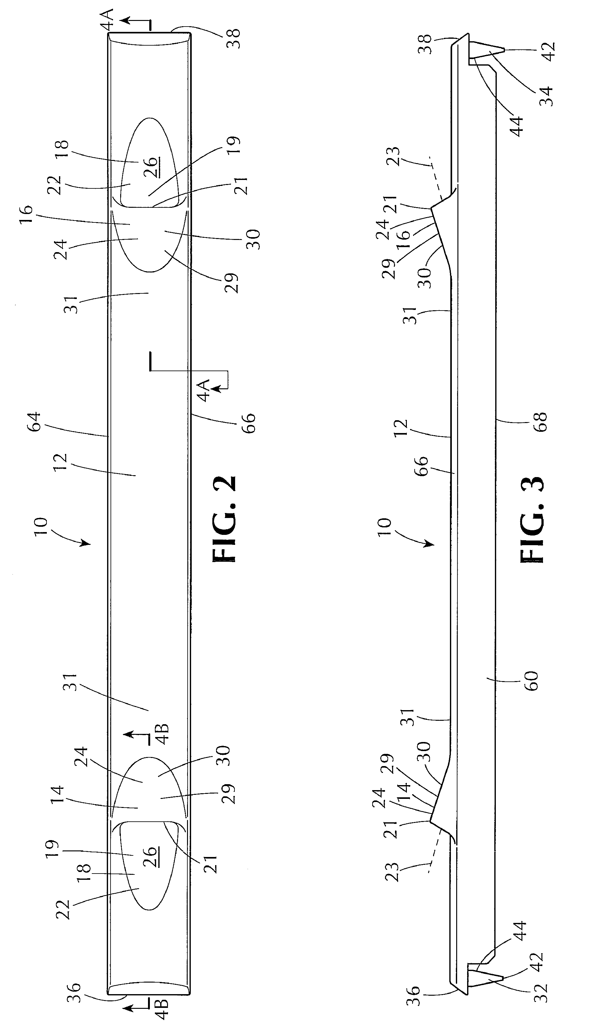
[0037]Referring to FIGS. 1-9, a 1U version of a blanking panel 10 constructed according to the invention includes a pair of ergonomic grips 14, 16 formed in a front wall 12 to facilitate secure, comfortable mounting and removal of the blanking panel 10 from a standardized electronic equipment rack or cabinet enclosure.

[0038]The blanking panel 10 has a generally rectangular configuration and is advantageously formed of a unitary molding of structural plastic material, and preferably an ABS plastic material having fire retardant characteristics.

[0039]Preferably, the blanking panel 10 has a lateral length, as measured from one end 36 to an opposite end 38, suitable for mounting in a standardized electronic equipment rack or cabinet enclosure, for example about 49 mm (i.e., about 19 inches). The above-mentioned ANSI / EIA-310-E standard specifies acceptable distances of 482.2 mm, 609.6 mm, or 782.2 mm, (i.e., about 19 inches, 24 inches, or 30 inches), with a tolerance of about + / −4 mm. Fu...


PUM


Abstract

A snap-mount blanking panel for an equipment rack or cabinet enclosure has ergonomic grips spaced laterally inward to permit comfortable and reliable mounting and removal of the blanking panel regardless of lateral clearance. Resiliently flexible sealing skirt members create a positive seal with adjacent electronic devices or blanking panels. Stacking structure enables stable stacking of multiple units outside a container. An off-set platform allows for mounting ambient atmospheric indicators or signage, or may be used as a writing surface. A cable pass-through is also provided.

Description

FIELD OF THE INVENTION[0001]The invention pertains to the field of standardized racks and cabinet enclosures for electronic equipment and, in particular, to blanking panels for standardized equipment racks and cabinet enclosures.BACKGROUND OF THE INVENTION[0002]Electronic devices, such as computer servers and related computer equipment, and other electronic devices, are commonly mounted in standardized racks and cabinet enclosures having spaced-apart, (typically vertical) mounting rails with a series of holes defining a plurality of uniformly-spaced mounting locations for mounting the electronic devices in a closely-spaced, stacked manner. Standards for such racks and cabinet enclosures have been published by various trade organizations, including the Electronic Industries Alliance (EIA 310-D), the International Electrotechnical Commission (IEC 60297), and the Deutsches Institut für Normung e.V. (DIN 41494 SC48D), which standards are hereby incorporated by reference.[0003]Electronic...

Claims


Application Information

Patent Timeline
Patent Type & Authority Patents(United States)
IPC IPC(8): A47F7/00
CPCH05K7/1488H05K7/1461
Inventor SEMPLINER, ARTHUR T.MERCHANT, BERKELEY T.
Owner AQUILA INC
Learn More