Intravascular stent with inverted end rings

a stent and end-ring technology, applied in the field of vascular repair devices, to achieve the effect of reducing the stent-to-shoulder distance, maintaining a pristine stent deployment, and being highly flexibl

Inactive Publication Date: 2011-06-14
ABBOTT CARDIOVASCULAR
View PDF108 Cites 49 Cited by
  • Summary
  • Abstract
  • Description
  • Claims
  • Application Information

AI Technical Summary

Benefits of technology

The present invention is directed to an intravascular stent that has an inverted cylindrical end ring configuration incorporated into the stent pattern on at least one of a proximal end and a distal end of the stent, which helps in reducing the stent-to-shoulder distance as well as delivering therapeutic drug to the peri-stent area while maintaining a pristine stent deployment. The stent also is highly flexible along its longitudinal axis to facilitate delivery through tortuous body lumens, but which is stiff and stable enough radially in its expanded condition to maintain the patency of a body lumen such as an artery when the stent is implanted therein.
Further, because of the positioning of the links, and the fact that the links do not expand or stretch when the stent is radially expanded, the overall length of the stent is substantially the same in the unexpanded and expanded configurations. In other words, the stent will not substantially shorten upon expansion. The inverted cylindrical end rings of the present invention likewise play a significant role in preventing the substantial shortening of the stent upon expansion due to the ability of the inverted cylindrical end rings to undergo complete expansion when the stent is in an implanted diameter.

Problems solved by technology

While some of these stents are flexible and have the appropriate radial rigidity needed to hold open a vessel or artery, there typically is a tradeoff between flexibility and radial strength and the ability to tightly compress or crimp the stent onto a catheter so that it does not move relative to the catheter or dislodge prematurely prior to controlled implantation in a vessel.

Method used


Image

  • Intravascular stent with inverted end rings
  • Intravascular stent with inverted end rings
  • Intravascular stent with inverted end rings

Examples


Embodiment Construction

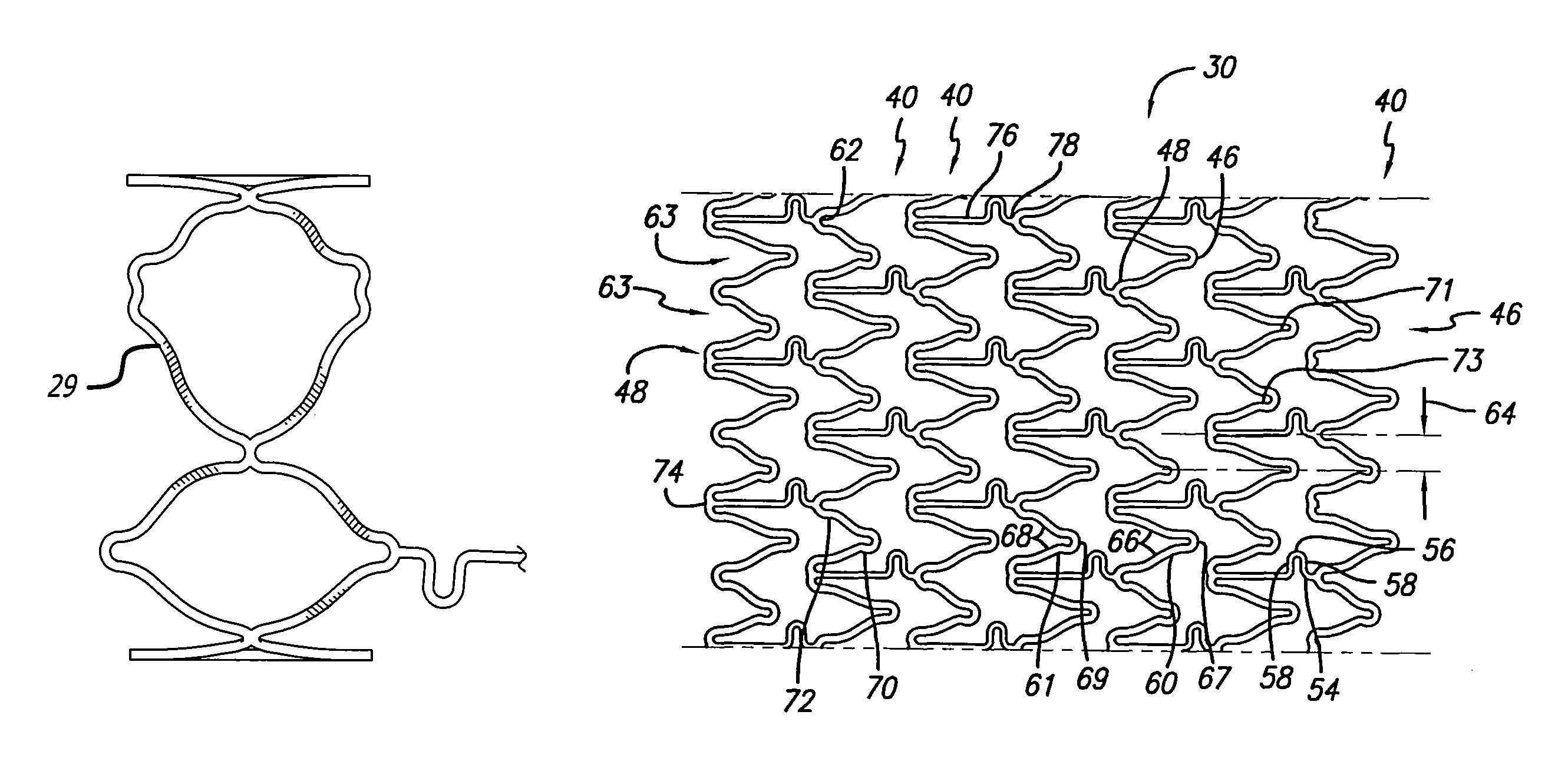
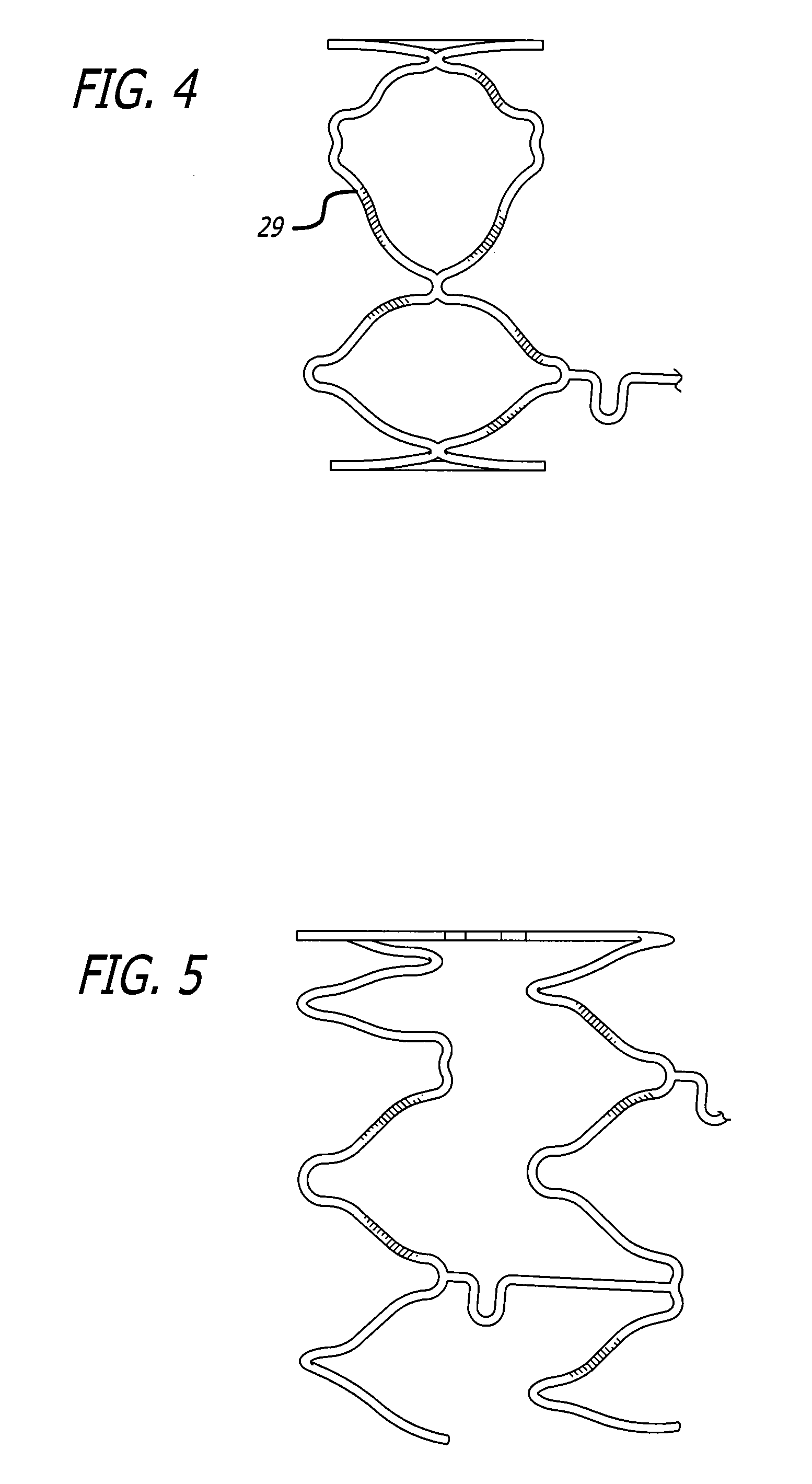
The present invention stent improves on existing stents by providing a longitudinally flexible stent having a plurality of inverted cylindrical end rings coupled at least in part to a plurality of adjacent cylindrical rings that can be in the form of mirror images of one another such that a symmetrical configuration is present on at least one of a proximal end and a distal end of the stent. In addition to providing longitudinal flexibility, the stent of the present invention also provides radial rigidity and a high degree of scaffolding of a vessel wall, such as a coronary artery. Further, the inverted end ring configuration of the present invention stent aims at reducing the stent-to-shoulder distance as well as delivering therapeutic drugs to the peri-stent area while maintaining a pristine stent deployment.

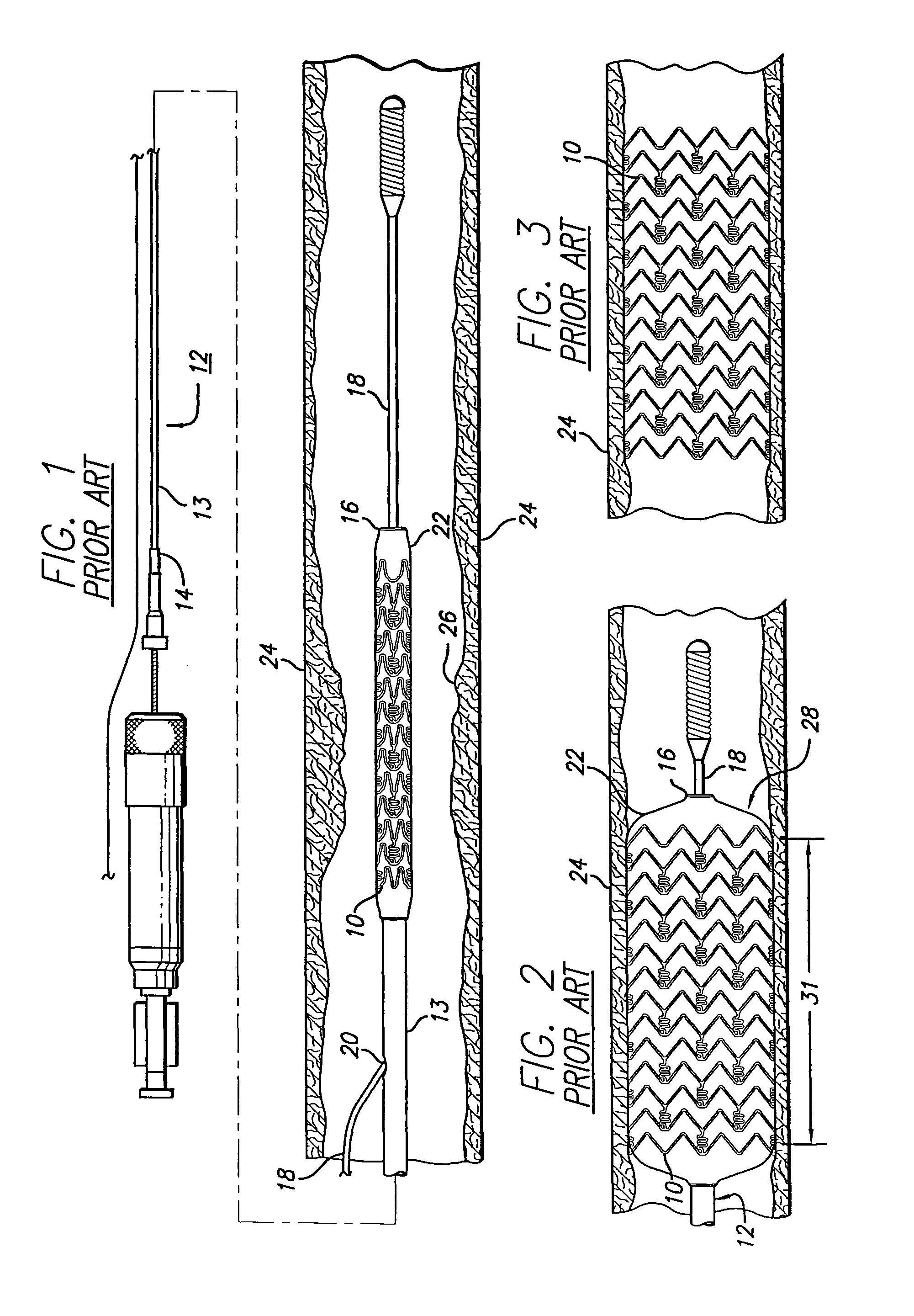
Before describing in detail an exemplary embodiment of a stent in accordance with the present invention, it is instructive to briefly describe a typical stent implantation proc...


PUM


Abstract

The invention is directed to an expandable stent for implanting in a body lumen, such as a coronary artery, peripheral artery, or other body lumen. The invention provides for an intravascular stent having a plurality of cylindrical rings connected by undulating links. A plurality of inverted cylindrical end rings can be coupled at least in part to a plurality of adjacent cylindrical rings in the form of mirror images such that a symmetrical configuration is present on at least one of a proximal end and a distal end of the stent. The stent has a high degree of flexibility in the longitudinal direction, yet has adequate vessel wall coverage and radial strength sufficient to hold open an artery or other body lumen. The inverted end ring configuration of the stent aims at reducing the stent-to-shoulder distance as well as delivering therapeutic drug to the peri-stent area while maintaining a pristine stent deployment.

Description

BACKGROUND OF THE INVENTIONThe invention relates to vascular repair devices, and in particular intravascular stents, which are adapted to be implanted into a patient's body lumen, such as a blood vessel or coronary artery, to maintain the patency thereof. Stents are particularly useful in the treatment of atherosclerotic stenosis in arteries and blood vessels.Stents are generally tubular-shaped devices which function to hold open a segment of a blood vessel or other body lumen such as a coronary artery. They also are suitable for use to support and hold back a dissected arterial lining that can occlude the fluid passageway. At present, there are numerous commercial stents being marketed throughout the world. For example, the prior art stents depicted in FIGS. 1-3 have multiplex cylindrical rings connected by one or more undulating links. While some of these stents are flexible and have the appropriate radial rigidity needed to hold open a vessel or artery, there typically is a trade...

Claims


Application Information

Patent Timeline
Patent Type & Authority Patents(United States)
IPC IPC(8): A61F2/06
CPCA61F2/91A61F2/915A61F2002/91508A61F2002/91516A61F2230/0054A61F2002/91533A61F2002/91558A61F2002/91575A61F2002/91525
Inventor PIENKNAGURA, CARLA ROSA
Owner ABBOTT CARDIOVASCULAR
Why Eureka
Try Eureka