
Multicast control

a control system and multicast technology, applied in television systems, two-way working systems, data switching networks, etc., can solve the problems of wasting massive amounts of bandwidth and the multicast stream keeps flowing, and achieve the effect of network bandwidth

Active Publication Date: 2011-06-14
TELEFON AB LM ERICSSON (PUBL)
View PDF17 Cites 3 Cited by
  • Summary
  • Abstract
  • Description
  • Claims
  • Application Information

AI Technical Summary

Benefits of technology

The present invention is about how to save bandwidth in a system that controls the delivery of digital information to terminals. The invention detects unused bandwidth consumption and prevents the transportation of information that is not needed by the terminals. This frees up network bandwidth for broadband operators, without interfering with existing standards. The invention optimizes bandwidth usage by disabling terminals that are not actively using the information. The method involves receiving a signal indicating de-activation of the terminal, sending a signal to the network, and stopping the delivery of the multicast stream. This allows the network to use the bandwidth for other purposes. The invention uses existing standards and does not break any new ones. Overall, the invention helps to make efficient use of network bandwidth.

Problems solved by technology

By not turning off the Set Top Box, the multicast stream keeps flowing, wasting massive amounts of bandwidth, especially in night-time.

Method used


Image

  • Multicast control
  • Multicast control
  • Multicast control

Examples


first embodiment

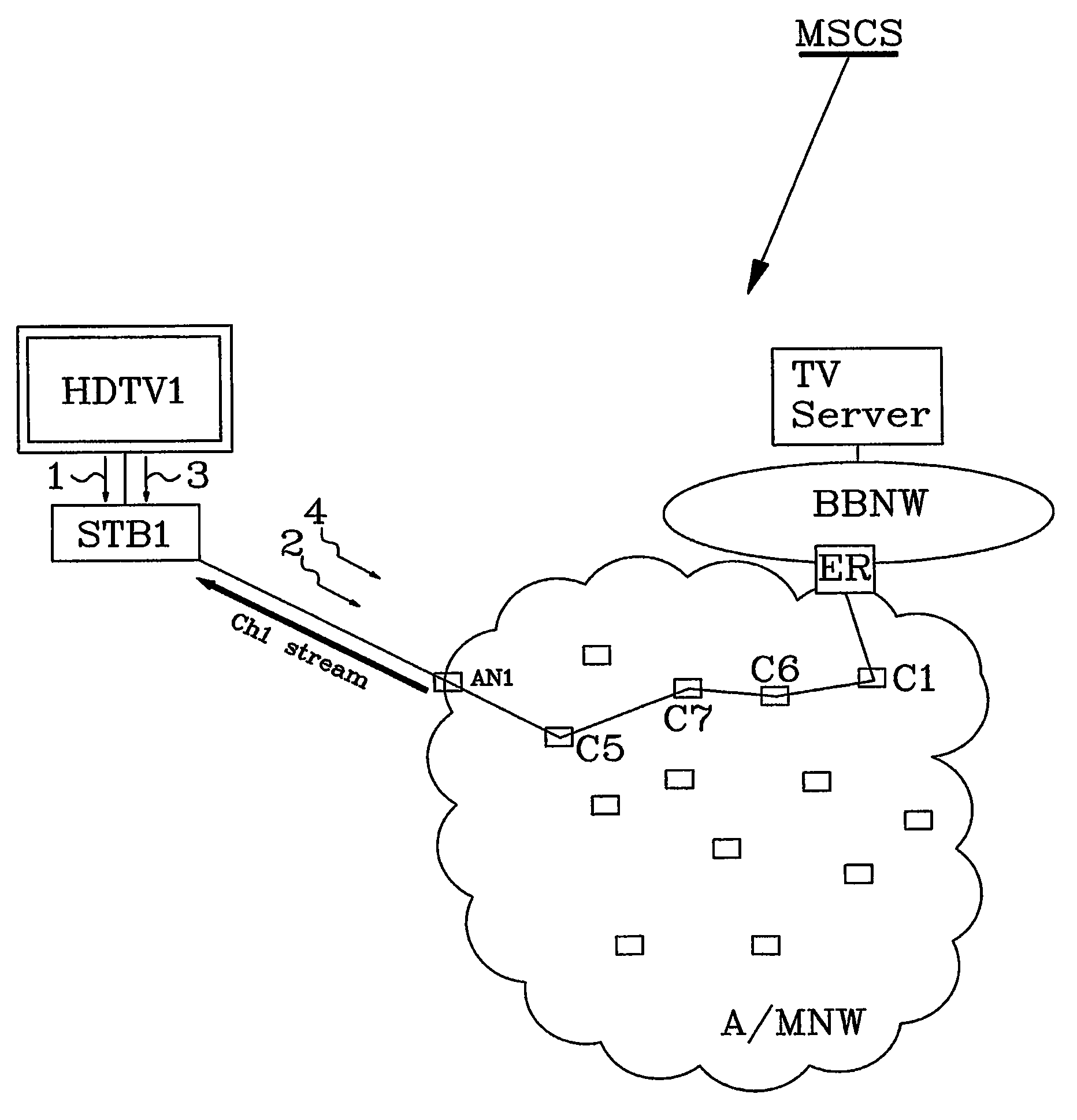
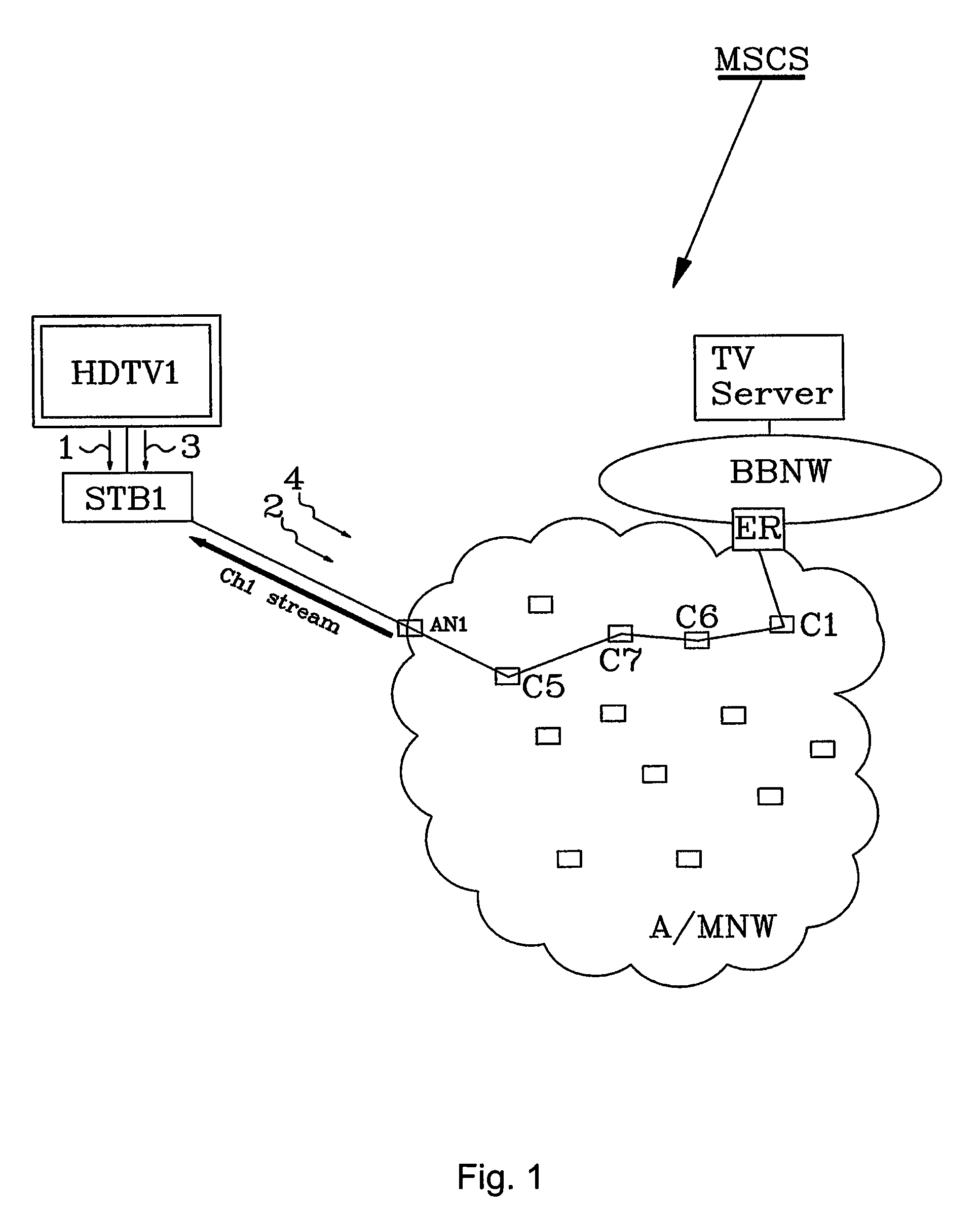
[0028]As a continuation of this first embodiment, the TV set again is turned on, for example if the set was turned off in the evening and again turned on in the morning. The method then comprises the following further steps:

[0029]The Set Top Box STB1, that continuously monitors the terminal status received from the terminal HDTV1, detects an activation signal 3 from the terminal, meaning that the TV Set again has been turned on.[0030]The Set Top Box sends an IGMP join report signal 4 requesting last viewed channel i.e. CH1 to the AN1 in the Broadband Network. The signal 4 is forwarded from AN1 through the network via for example the concentrators C5, C7, C6 and C1 all the way until it reaches an originating (also called start) point of the CH1 stream in the broadband network. The ER is the originating point of the CH1 stream destined for STB1 i.e. this is the first point along the path were the CH1 stream was found. The IGMP message is only forwarded as far as needed, it stops at th...

second embodiment

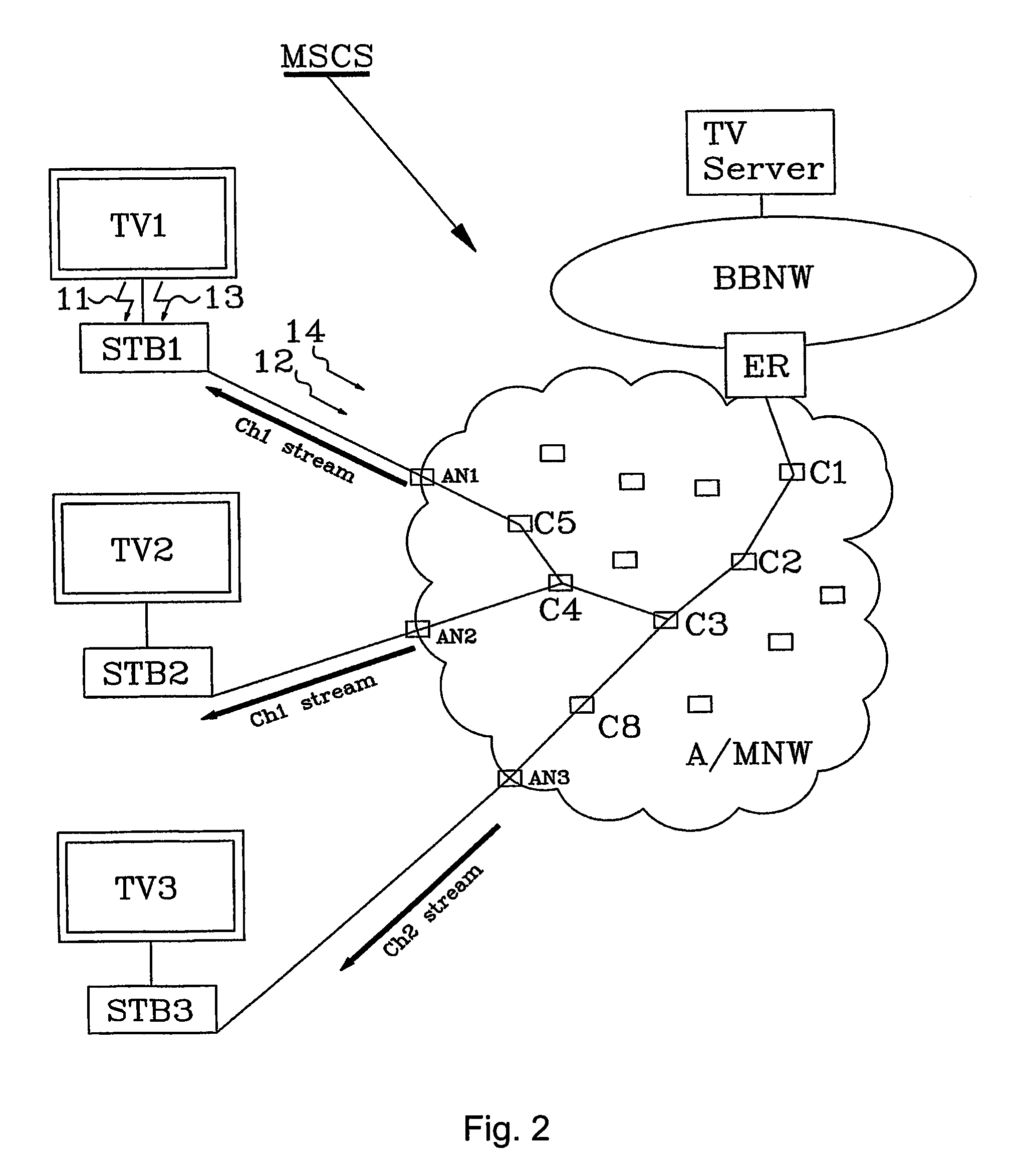
[0040]As a continuation of the second embodiment, the TV set again is turned on. The method then comprises the following further steps:[0041]The Set Top Box STB1 detects an activation signal 13, meaning that the TV Set again has been turned on.

[0042]The Set Top Box sends an IGMP join report signal 14 requesting last viewed channel i.e. CH1 to the AN1 in the Broadband Network.[0043]The IGMP join report signal 14 signal is forwarded from AN1 through the network towards ER until it reaches a point where the CH1 stream is found. Since the Ch1 stream still is sent to STB2, C4 is the first (start) point along the path where the CH1 stream was found.[0044]C4 starts multicasting the CH1 stream towards STB1 using the path C4-C5-AN1.[0045]STB1 receives the CH1 stream from AN1 and forwards a rendered TV image to TV1.

[0046]FIG. 3 shows some examples of possible terminal configurations that can be used to put the invention into practice. The figure discloses three configurations A, B and C. The ...


PUM


Abstract

A method and arrangement for optimizing bandwidth usage in a Multicast Services Control System (MSCS), which transports digital information in a multicast stream from a broadband network to a Set Top Box (STB) connected to a terminal TV. When the terminal TV is disabled, and can no longer utilize the multicast stream, the terminal TV sends a terminal status signal to the STB indicating deactivation of the terminal TV. In response, the STB sends an IGMP leave report signal to the broadband network, which then ceases its transmission of the multicast stream to the STB.

Description

FIELD OF INVENTION[0001]The present invention relates to methods and arrangements to optimize bandwidth usage in a multicast services control system for digital information transport.BACKGROUND[0002]Multicast is the way IP TV is distributed in broadband networks. Set Top Boxes have an important role of receiving and rendering the TV image for the TV sets. A Set Top Box in broadband networks does this by standardized speaking IGMP (Internet Group management Protocol) to the broadband network. The Protocol starts and stops TV streams as well as channel changes. Traffic management is important in digital networks. Traffic management involves the controlling and scheduling of traffic through paths established through a network. The traffic can include audio, video, or any form of digital information. Channel streaming is used to take a group of digital information services and configure them to flow down into a digital network into several channels so as to get the digital information c...

Claims


Application Information

Patent Timeline
Patent Type & Authority Patents(United States)
IPC IPC(8): H04J3/26H04N7/173
CPCH04L12/66H04L12/185
Inventor KOLHI, JOHAN
Owner TELEFON AB LM ERICSSON (PUBL)
Learn More