Inflation system for tires

Active Publication Date: 2011-06-21
AIRGO IP
View PDF12 Cites 48 Cited by
  • Summary
  • Abstract
  • Description
  • Claims
  • Application Information

AI Technical Summary

Benefits of technology

[0007]The lubrication trap preferably provides a pressure relief pathway adjacent the fluid conduit, the pressure relief pathway mitigating migration of a lubricant from the interior of the hubcap to the exterior of the hubcap while conducting pressurized fluid from interior of the hubcap to the exterior of the hubcap when the pressurized fluid within the interior of the hubcap attains a predetermined pressure level.
[0008]In an alternate preferred embodiment, a tire inflation system incorporates at least an axle housing a pressurized fluid, a hubcap supported by the axle and having an interior and an exterior, a rotary union axially aligned with the axle and mounted to the hubcap from the exterior of the hubcap, and a hollow core bushing axially aligned with the axle, disposed between the rotary union and the hubcap, and placed adjacent the hubcap from the exterior of the hubcap. Preferably, the alternate preferred embodiment further includes at least a bearing disposed between a face of the fluid conduit and the through tee, and a lubrication trap providing at least a pressure relief pathway adjacent the fluid conduit, the pressure relief pathway mitigating migration of a lubricant from the interior of the hubcap to the exterior of the hubcap while conducting pressurized fluid from the interior of the hubcap to the exterior of the hubcap when the pressurized fluid within the interior of the hubcap attains a predetermined pressure level.

Problems solved by technology

Pressure responsive valves are employed between each rotary union assembly and its associated tires so that upon the occurrence of a leak in one of the tires, the resulting pressure loss will cause one of the valves to open and allow air flow from the rotary union assembly to pass therethrough to the leaking tire.

Method used


Image

  • Inflation system for tires
  • Inflation system for tires
  • Inflation system for tires

Examples


Embodiment Construction

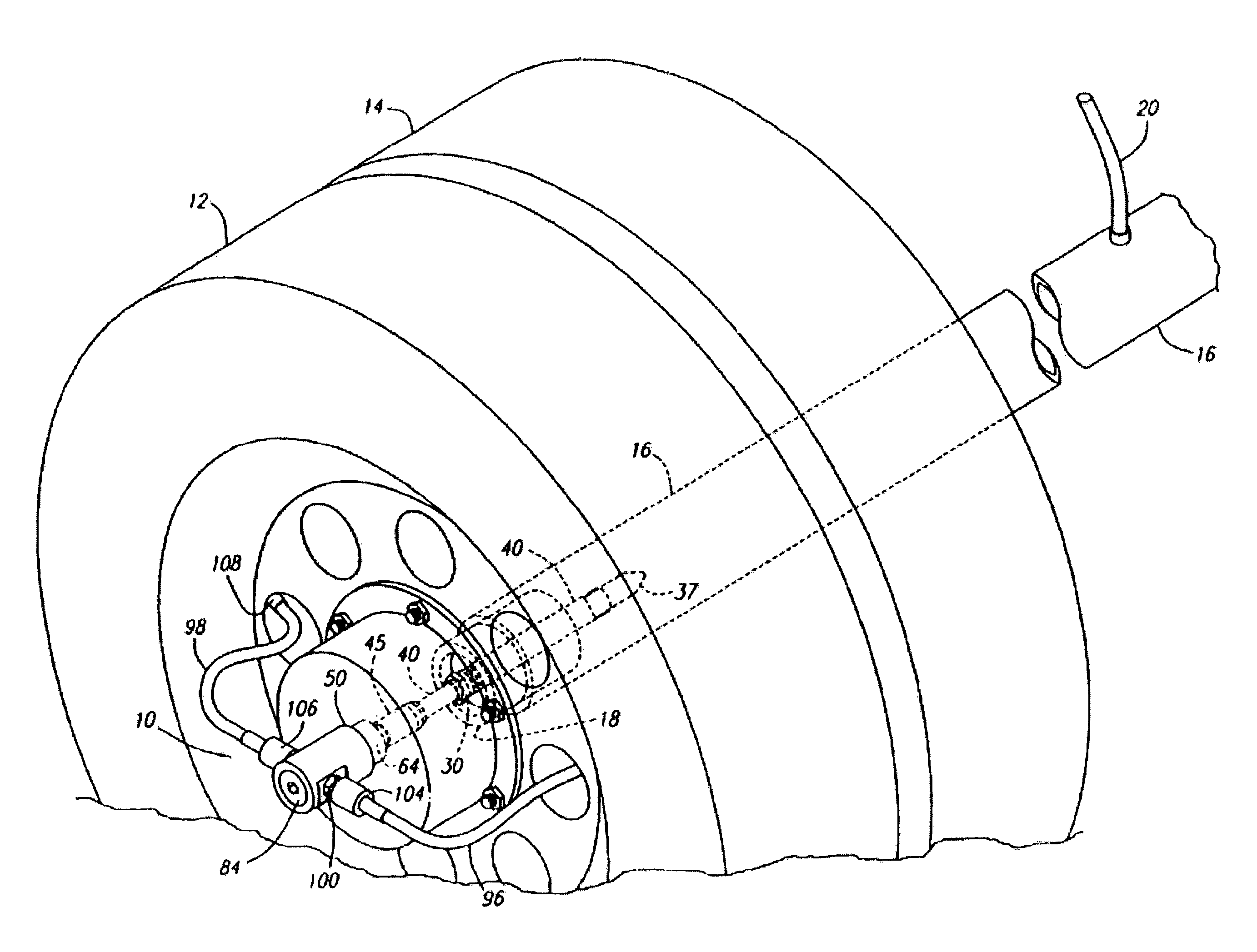
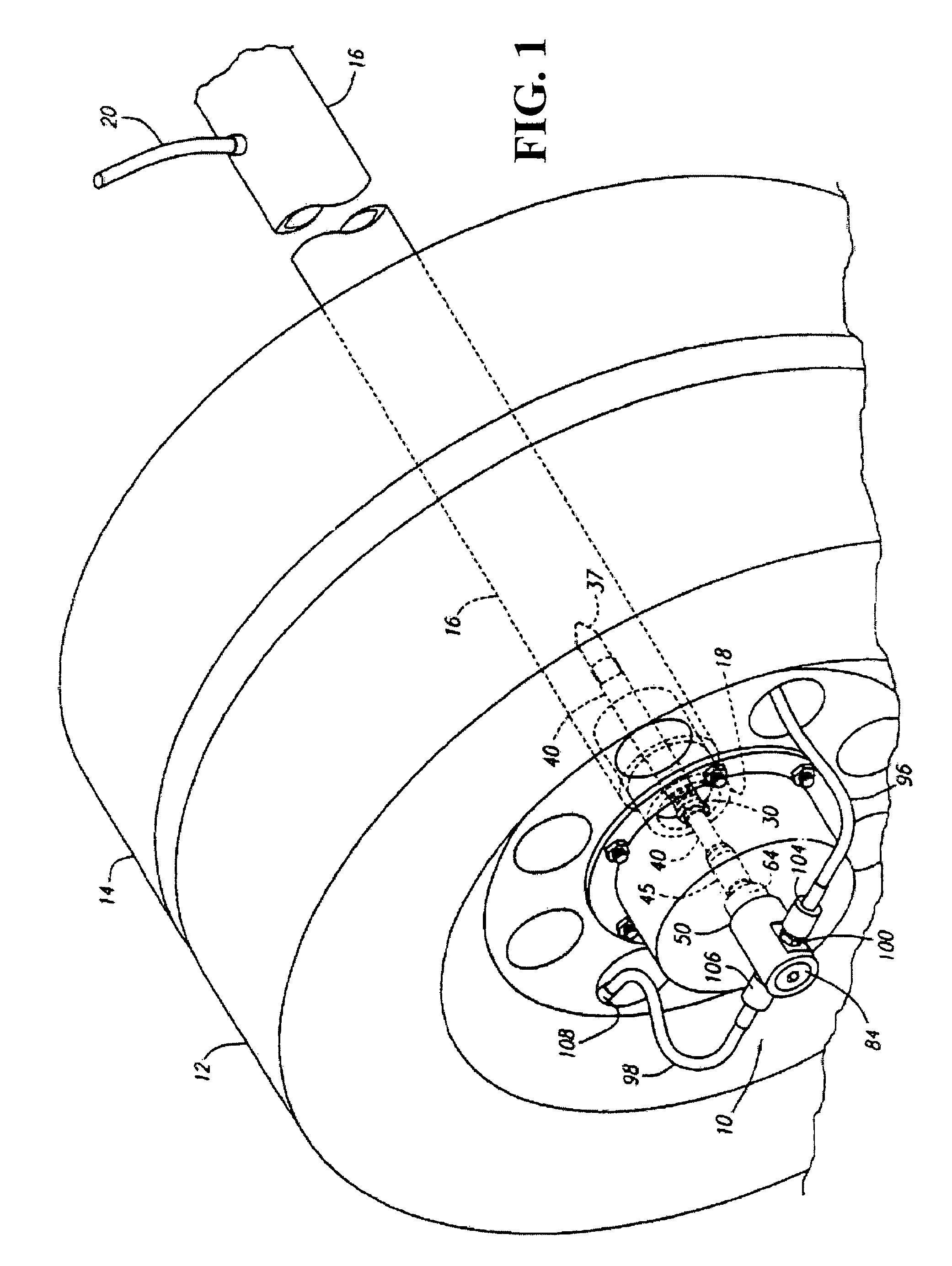
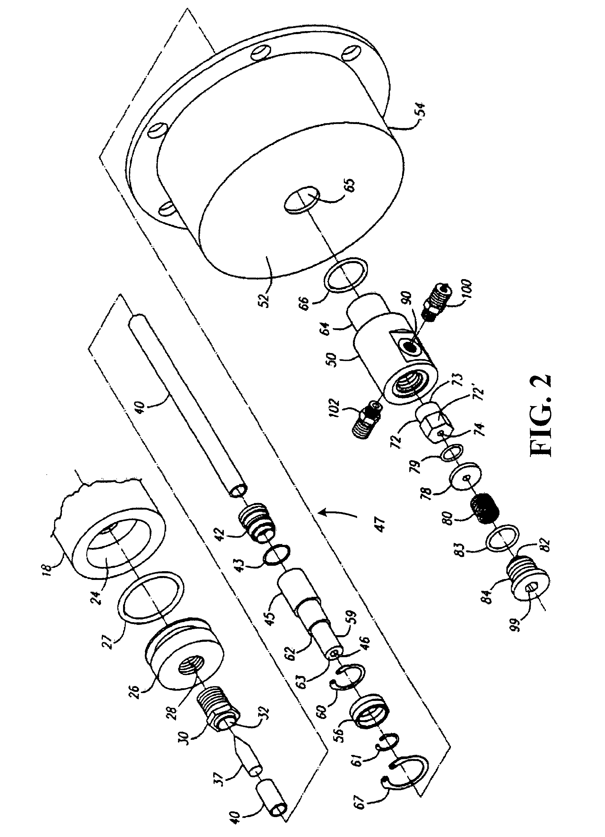
[0034]It will be readily understood that elements of the present invention, as generally described and illustrated in the Figures herein, could be arranged and designed in a wide variety of different configurations. Referring now in detail to the drawings of the preferred embodiments, the rotary union assembly 10 (also referred to herein as assembly 10) of the first preferred embodiment, while useable on a wide variety of movable vehicles employing stationary axles for automatically maintaining the inflation pressure of the pneumatic tires thereon, is particularly adapted for use on tractor trailers. Accordingly, the assembly 10 of the first preferred embodiment will be described in conjunction with a pair of adjacent vehicle tires 12 and 14 mounted on a stationary tractor trailer axle 16 (also referred to herein as trailer axle 16, and axle 16). While identical rotary union assemblies 10 are provided at the end of each axle on the trailer to maintain the inflation pressure of the t...


PUM


Abstract

Preferably, an embodiment of a tire inflation system includes at least an axle housing a pressurized fluid, a hubcap supported by the axle and having an interior and an exterior, a rotary union axially aligned with the axle and mounted to the hubcap from the exterior of the hubcap, and a lubrication trap axially aligned with the axle, supporting the rotary union and secured to the hubcap from the exterior of the hubcap for rotation with the hubcap. In another embodiment, a tire inflation system includes at least an axle housing a pressurized fluid, a hubcap supported by the axle and having an interior and an exterior, a rotary union axially aligned with the axle and mounted to the hubcap from the exterior of the hubcap, and a bushing axially aligned with the axle and disposed between the rotary union and the hubcap.

Description

FIELD OF THE INVENTION[0001]The present invention relates to the field of tire inflation. More particularly, the present invention relates to the inflation of tires supporting tractor trailers, even while the trailers are traveling along a roadway.BACKGROUND OF THE INVENTION[0002]The present invention relates to an improved rotary union for use in a central tire inflation system for automatically maintaining the inflation pressure of the pneumatic tires on moving vehicles such as tractor trailers. Central tire inflation systems employed on typical tractor trailers utilize the air compressor on the tractor as a source of pressurized air to fill a leaking tire while the trailer is in motion. The compressor directs air to the reserve air brake tank on the trailer, which generally corresponds to the range of typical inflation pressures in the tires used on trailers. Air from the reserve air brake tank is first directed to the braking system to maintain the air pressure in the braking sy...

Claims


Application Information

Patent Timeline
Patent Type & Authority Patents(United States)
IPC IPC(8): B60C23/02
CPCB60C23/003B60C23/00318B60C23/00345B60C23/00354B60C23/00363
Inventor INGRAM, ANTHONY L.BURGESS, CALVINPENWELL, MICHAEL H.ROBERTS, PATRICK E.
Owner AIRGO IP
Why Eureka
Try Eureka