Pillar trim for motor vehicle

a technology for motor vehicles and pillars, applied in the direction of roofs, doors, pedestrian/occupant safety arrangements, etc., can solve the problems of breaking of bosses, and affecting the safety of passengers, and achieve the effect of smooth fitting

Inactive Publication Date: 2011-06-21
DAIKYONISHIKAWA CORP +1
View PDF5 Cites 18 Cited by
  • Summary
  • Abstract
  • Description
  • Claims
  • Application Information

AI Technical Summary

Benefits of technology

[0018]With the above configuration, since each adjacent pair of guide platforms raised upward beyond the upper end of the pillar trim body are joined to each other by a connecting part, that region of the pillar trim body around the guide platforms has a high rigidity. Therefore, the upper end part of the pillar trim body can well withstand the reaction force upon inflation of the airbag.
[0041]With the above configuration, a clearance into which the peripheral edge of the insertion opening in the pillar of the vehicle body can be inserted is left between the insertion part and the plate-shaped rib so that when the insertion part is inserted into the insertion opening, the plate-shaped rib does not interfere with the pillar. Thus, the pillar trim can be smoothly fitted to the pillar of the vehicle body without the plate-shaped rib interfering with the pillar.

Problems solved by technology

However, if the upper end part of the pillar trim body has a high rigidity, this causes a problem in safety that in case where the passenger's head hits the upper end part of the pillar trim body in a side collision, the passenger might be seriously damaged.
This might cause breakage of the boss from its basal end close to the pillar trim body.
Also in this case, the positioning pin might break likewise upon inflation of the airbag.
Furthermore, in the structure in which a plurality of guide platforms are disposed at spaced intervals as in the above known airbag systems, the inflating airbag cannot be supported between the guide platforms.
Therefore, its reaction force is concentrated on the guide platforms, which might break the guide platforms.

Method used


Image

  • Pillar trim for motor vehicle
  • Pillar trim for motor vehicle
  • Pillar trim for motor vehicle

Examples


embodiment 1

Effects of Embodiment 1

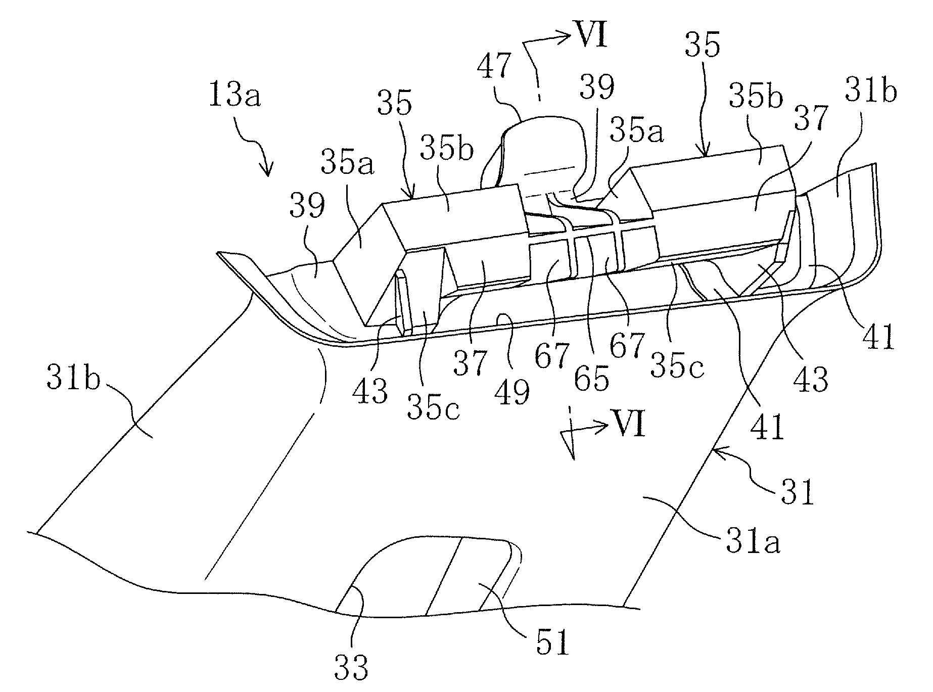
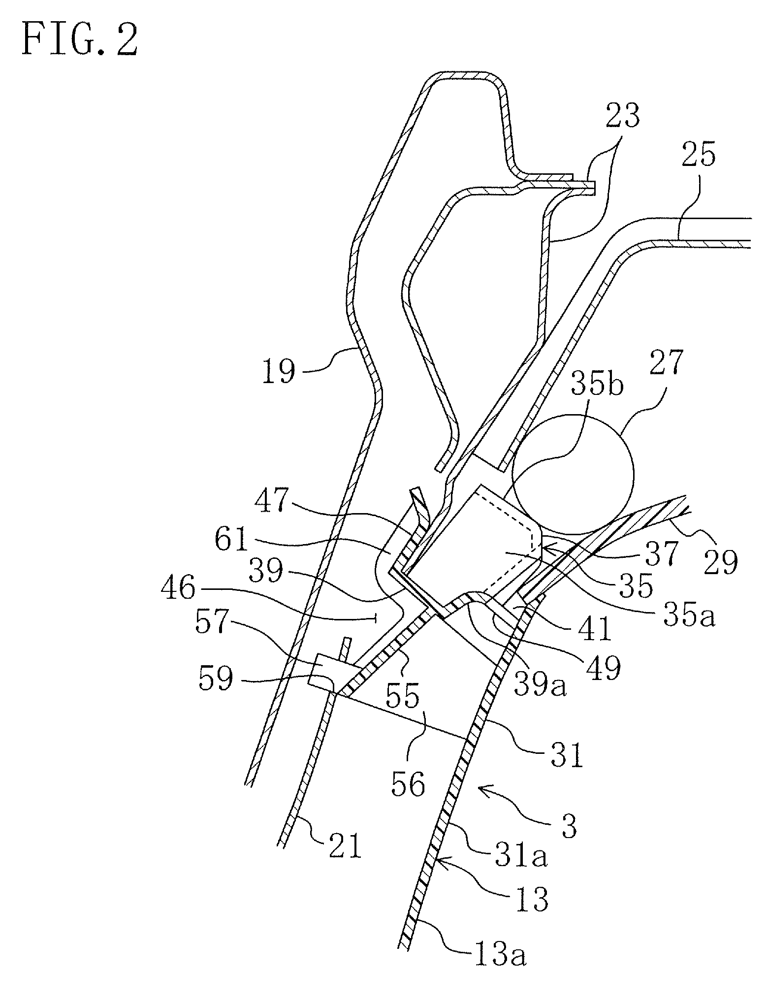
[0068]In the B-pillar trim 13 for a motor vehicle according to Embodiment 1, two guide platforms 35 and 35 rising up beyond the upper end of the pillar trim body 31 of the upper pillar trim 13a are joined to each other by the portion of the plate-shaped part 39 serving as a connecting part. Therefore, the upper region of the pillar trim body 31 is increased in rigidity and can thereby well withstand the reaction force upon inflation of the airbag 27.

[0069]Furthermore, a through hole 49 is formed so as to be surrounded by the portion of the plate-shaped part 39 joining both the basal ends of the guide platforms 35 and 35, portions of both the guide platforms 35 and 35 and the vehicle interior-side surface of the front part 31a of the pillar trim body 31 to vertically pass through the groove 41, whereby the pillar trim body 31 is separated from the portion of the plate-shaped part 39 located between both the guide platforms 35 and 35 and the portions of both the...

embodiment 2

Effects of Embodiment 2

[0081]Also the B-pillar trim 13 for a motor vehicle according to Embodiment 2 can achieve the same effects as in Embodiment 1. In addition, Embodiment 2 can achieve the following particular effects.

[0082]Particularly, the basal ends of both the guide platforms 35 and 35 are joined to each other by the plate-shaped part 39 (connecting part) and the first and second ribs 65, 67 and 67 are formed between both the guide platforms 35 and 35. Therefore, the rigidities of the plate-shaped part 39 and the guide platforms 35 and 35 are increased, whereby the inflating airbag 27 can be firmly supported not only by the guide platforms 35 and 35 but also by the first and second ribs 65, 67 and 67.

[0083]Furthermore, the reaction force upon inflation of the airbag 27 is distributed to the guide platforms 35 and 35 and the first and second ribs 65, 67 and 67. Therefore, stress concentration on the guide platforms 35 and 35 can be reduced to prevent breakage of the guide plat...


PUM


Abstract

A pillar trim on the vehicle-interior side of a pillar includes a pillar trim body located below an airbag and connected at its upper end part to the lower end of a top sealing member. A plurality of guide platforms are raised from the upper end part of the pillar trim body at spaced intervals in the vehicle front-to-rear direction to guide the inflation of the airbag towards the vehicle interior. The basal ends of each adjacent guide platforms are joined by a connecting part between the adjacent guide platforms. A groove for receiving the lower end of the top sealing member is formed between the vehicle-interior sides of the guide platforms and the pillar trim body. A through hole is vertically formed at least between the connecting part and the pillar trim body to open into the groove.

Description

CROSS-REFERENCES TO RELATED APPLICATIONS[0001]This application claims priority under 35 USC 119 to Japanese Patent Applications Nos. 2007-145815, 2007-145816 and 2007-145891 all filed on May 31, 2007, the entire contents of all of which are incorporated herein by reference.BACKGROUND OF THE INVENTION[0002](a) Field of the Invention[0003]This invention relates to pillar trims for motor vehicles fitted with airbags as safety measures in case of side collisions.[0004](b) Description of the Related Art[0005]Various airbag systems for protecting motor vehicle passengers' heads in case of a side collision have been conventionally known. Among such airbag systems are known those in which an airbag is placed on the vehicle interior side of the side body of a motor vehicle and towards the roof to extend in a front-to-rear direction of the vehicle body from a front pillar (hereinafter, referred to as an A-pillar) through a center pillar (hereinafter, referred to as a B-pillar) to the vicinity...

Claims


Application Information

Patent Timeline
Patent Type & Authority Patents(United States)
IPC IPC(8): B60R21/16B60J7/00B60R21/213
CPCB60R13/025B60R21/213B60R13/0275B60R13/06B60R2021/161B60R2013/0287B60R2013/0293
Inventor MATSUOKA, DAISUKEONISHI, IKUKO
Owner DAIKYONISHIKAWA CORP
Why Eureka
Try Eureka