Anti-rotation pipe locator and holder

a locator and anti-rotation technology, applied in the direction of branching pipes, mechanical devices, adjustable joints, etc., can solve the problems of reducing affecting the service life of the locator, and unable to adequately restrain the movement along the length of the pipe, so as to achieve wide and stable support and make the separation difficult

Active Publication Date: 2011-06-21
RELIANCE WORLDWIDE CORP
View PDF26 Cites 19 Cited by
  • Summary
  • Abstract
  • Description
  • Claims
  • Application Information

AI Technical Summary

Benefits of technology

[0005]Very briefly described, a plumbing strap is fastened to a building. A tubular insert is placed through a hole in a strap with one or more posts on the tubular insert aligning with cut-outs in the periphery of the opening to restrict rotation of the tubular insert relative to the strap. A flange on one end of the tubular insert abuts the strap to restrict longitudinal motion of the tubular insert. Latches on the tubular insert extend through the hole in the strap to engage the side of the strap opposite a flange and further restrict longitudinal movement of the tubular insert. A collar is placed over the distal end of the tubular insert and a pipe extends through the tubular insert and collar. The tubular insert has a base adjacent the flange and a skirt distal from the flange. Longitudinal slits in the base and skirt define resilient members in the base and in the skirt that extends from about the middle of the tubular insert but in opposing directions, to separate the members from the tubular insert so the members can move inward. The collar screws onto the tubular insert causing abutting surfaces on the collar and on the resilient members to force the resilient members inward to grip the pipe and restrain longitudinal and rotational movement of the pipe relative to the tubular insert and strap.
[0009]The flange abuts the strap to prevent longitudinal movement along one axis, and latches are provided that extend through the hole in the strap through which the tubular insert is installed in order to engage the opposing side of the strap to restrain movement in the opposing axial direction. The latches preferably have a stepped or barbed portion located to engage the side of the strap opposite the flange to further restrain the tubular insert from being removed from the hole in the strap. The latches are advantageously flexible enough so the distal end of each latch bends inward toward the longitudinal axis of the tubular insert as the latches slide through the hole in the strap and then extend outward so the stepped or barbed portion engages the strap. Manually moving the distal ends of the latches inward disengages the stepped or barbed portions and allows removal of the latches and tubular insert from the strap.
[0010]The skirt is tubular so the pipe fits through the skirt. The skirt is threaded on its outside and is also slit along its length (i.e., parallel to the axis of the pipe) to form a collet having a plurality of resilient members that can be moved inward toward the pipe. The resilient members extend from the skirt toward the distal end of the skirt. A threaded collar fits over the distal end of the tubular insert so that it surrounds the slit portion of the skirt and is movable in an axial direction to engage the threaded portion of the skirt. A narrowing diameter or ramp on the collar squeezes these resilient members in the skirt inward to grip and hold the pipe as the threaded collar is tightened on the tubular insert. Unscrewing the collar allows the slit portions of the tubular insert to resume their original positions and loosens the frictional grip on the pipe.
[0012]Further, the tubular insert optionally has a tubular base interposed between the flange and skirt, with longitudinal slits in the base and alternating circumferential slots or openings through the flange in order to form resilient base members that can move toward the pipe. The resilient base members extend from an area near the skirt toward and preferably slightly beyond the flange, while the resilient skirt members extend in the opposite direction away from the flange. The free ends of the flexible base members optionally have defined contact areas to abut the pipe and advantageously those contact areas are located slightly beyond the flange in order to provide a wide and stable support for the pipe that extends through the tubular insert and collar. Inclined surfaces are placed on one or both of the collar and flexible base members so that movement of the collar toward the flange urges the flexible base members inward toward the pipe.
[0013]In use, the tubular insert and collar are slid over the end of a pipe, or at least the tubular insert is slid over the end of the pipe. The tubular insert and optionally the collar are inserted through the hole in the strap. Once installed around the pipe and assembled to the distal end of the tubular insert the collar is tightened so the slit portion of the skirt grips the pipe and prevents movement of the pipe along the axis of the pipe and tubular insert and rotational movement of the pipe relative to the tubular insert. Optionally, tightening the collar also causes the resilient bases members to move inward and grip the pipe at a location distant from the distal end of the skirt. Preferably the collar and resilient members have mating inclined surfaces so axial movement of the collar causes the inward gripping movement of the resilient members. Optionally, tightening the collar also urges the latches outward to further engage the slots or cut-outs in the strap. The collar is loosened if the axial position of the pipe relative to the strap and / or tubular insert needs adjustment. The tubular insert could be installed into the opening in the strap either before or after the pipe is passed through the tubular insert. The collar could be assembled to the tubular insert either before or after the pipe is passed through the tubular insert. Unscrewing the collar allows the pipe to be released and may allow the collar to be removed from the tubular insert. Optionally, the tubular insert and collar may be assembled during manufacture so they are installed in the strap as a unit. Further, the collar can be dimensioned relative to the tubular insert such that the collar can spin freely on the tubular insert without the threads engaging on the tubular insert and collar. Further, cooperating elements may be optionally be fashioned on one or both of the tubular insert or collar to make separation difficult once they have been assembled. Squeezing the ends of the latches inward allows the latches to pass through the hole in the strap so the tubular insert can be removed from the strap.

Problems solved by technology

Additionally, many methods involve the use of solder and hot appliances and open flames such as torches which introduce extra steps, hazards and liabilities into the process.
But these prior art devices can be difficult to install, and may not adequately restrain movement along the length of the pipe.
Restraining movement along the length of the pipe can be problematic because the pipe is typically held adjacent an elbow or 90° bend such as typically occurs when pipes extend along a wall and then outward to connect to a sink, tub, shower etc., and there is little room between the elbow and the wall within which to fit an apparatus that adequately restrains the desired movements of the pipe.

Method used


Image

  • Anti-rotation pipe locator and holder
  • Anti-rotation pipe locator and holder
  • Anti-rotation pipe locator and holder

Examples


Embodiment Construction

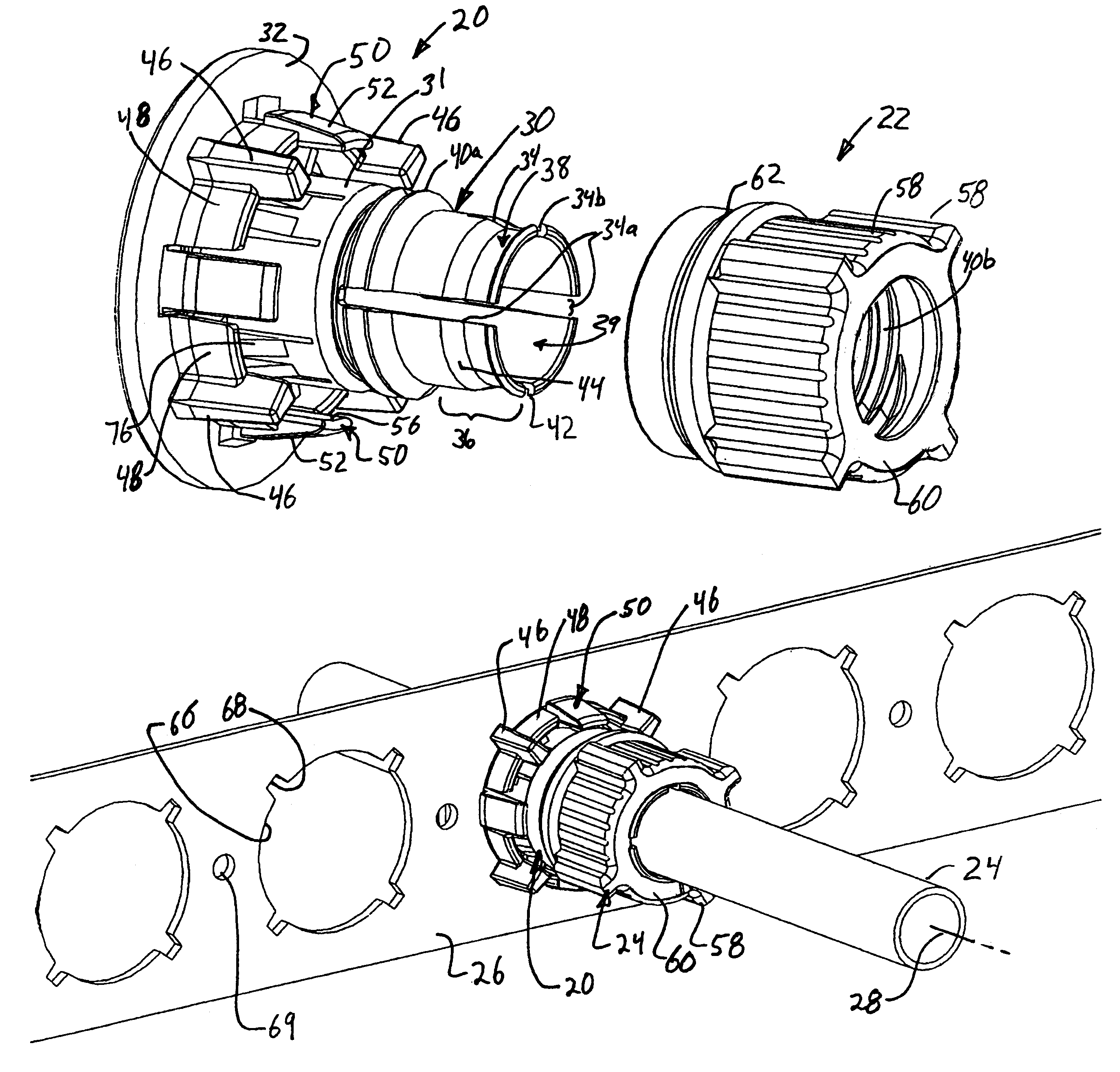
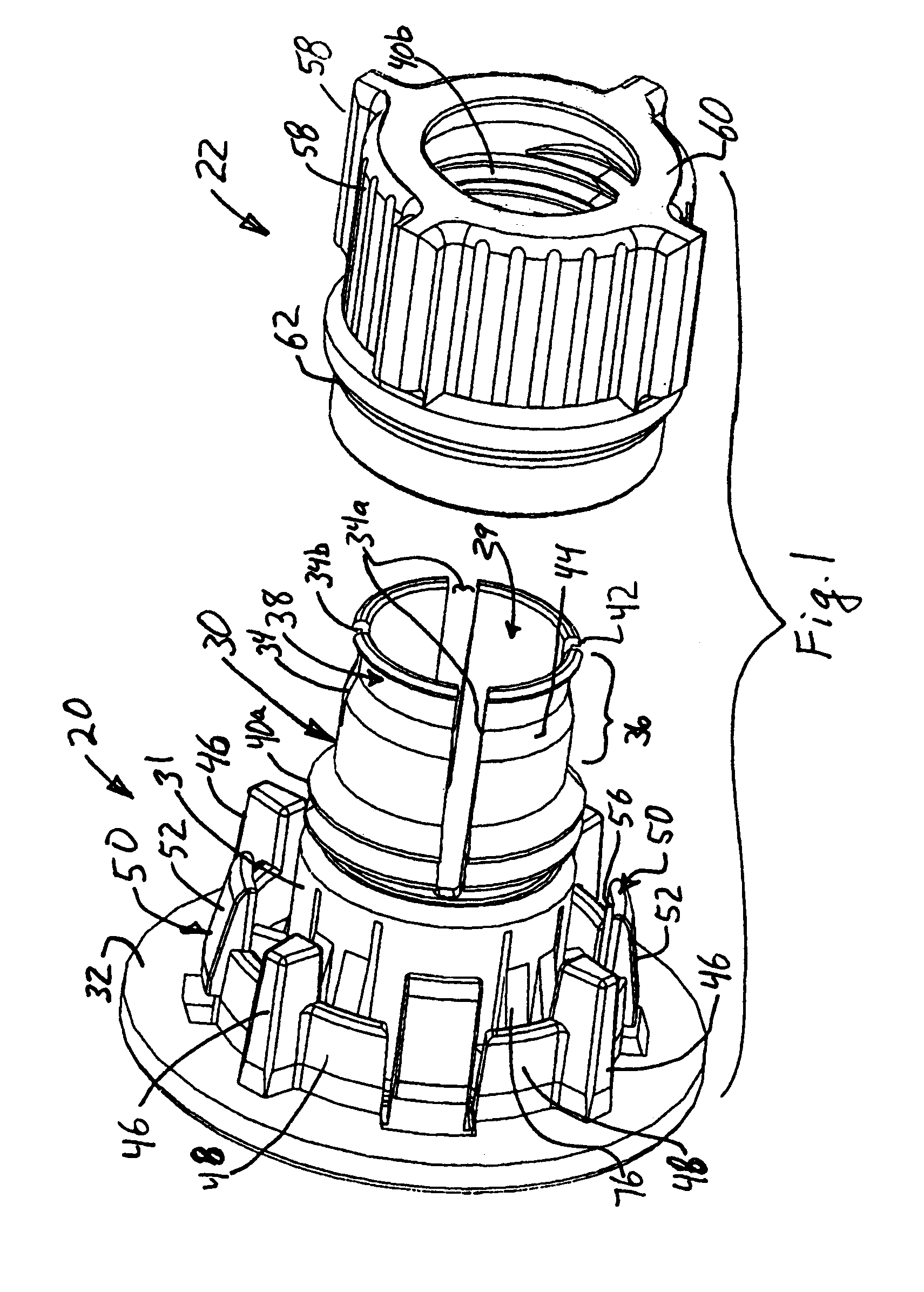
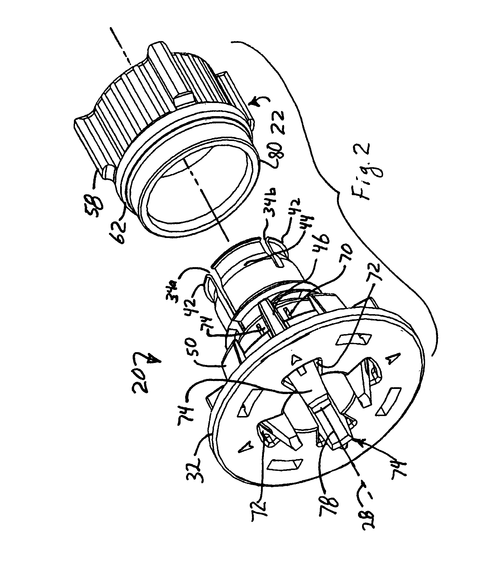
[0029]Referring to FIGS. 1-6, and primarily to FIGS. 1 and 4, an tubular insert 20 cooperates with a collar 22 to fasten pipe 24 to a support member, referred to herein as strap 26 that is in turn fastened to a building (not shown). The tubular insert 20 and pipe 24 preferably have a common longitudinal axis 28 when assembled, with the tubular insert having a passage 29 configured to allow passage of the pipe 24. The passage 29 is preferably of the same shape as the pipe and slightly larger than the pipe. Thus, for a cylindrical pipe 24 the passage 29 is also preferably cylindrical, but the shape of passageway 29 could be different, such as square, hexagonal, octagonal or other multi-sided cross-sectional shapes.

[0030]The tubular insert 20 has a tubular base 31 and a tubular skirt 30 extending along and encircling the longitudinal axis 28. Flange 32 is connected to the base 31 and generally perpendicular to the base 31 and skirt 30. The flange abuts strap 26 during use. The flange 3...


PUM


Abstract

A plumbing strap is fastened to a building. A tubular insert is placed through a hole in a strap with posts on the tubular insert aligning with cut-outs in the strap to restrict rotation of the tubular insert relative to the strap. A flange on one end of the tubular insert abuts the strap to restrict longitudinal motion of the tubular insert. Latches on the tubular insert extend through the hole in the strap to engage the side of the strap opposite the flange and further restrict longitudinal movement of the tubular insert. A collar is placed over the tubular insert and a pipe extends through the tubular insert and collar. The tubular insert has a base adjacent the flange and a skirt distal from the flange. Longitudinal slits in the base and skirt define resilient members in the base and in the skirt that extend in opposing directions, but that can move inward. The collar screws onto the tubular insert causing abutting surfaces on the collar and on the resilient members to force the resilient members inward to grip the pipe and restrain longitudinal and rotational movement of the pipe relative to the tubular insert and strap.

Description

CROSS-REFERENCE TO RELATED APPLICATIONS[0001]This application claims the benefit under 35 U.S.C. §119(e), of application Ser. No. 60 / 926,546, filed Apr. 27, 2007, the entire contents of which are incorporated herein by reference.BACKGROUND[0002]Pipes adapted to mate with a plumbing fixture such as a sink or the like typically extend upwardly between building studs and project laterally from the building's wall for connection to the plumbing fixture through fixture inlets such as shut-off valves. The pipes are preferably secured in place to prevent axial movement parallel to the pipes, rotation around the pipes, vertical movement upwardly and downwardly, and lateral movement sideways during use. The pipes are also preferably located a predetermined distance apart from each other for precise alignment with fixture inlets that are typically pre-formed in the plumbing fixtures.[0003]Traditional methods of securing pipes between studs use complex hardware such as bolted elbows, threaded ...

Claims


Application Information

Patent Timeline
Patent Type & Authority Patents(United States)
IPC IPC(8): F16L3/04
CPCF16L5/08E03C2001/028
Inventor GALLARDO, LUISBROWN, LARRY D.HART, DENNIS
Owner RELIANCE WORLDWIDE CORP
Why Eureka
Try Eureka