Mounting device for a glazing panel and method of its use

a technology of mounting device and glazing panel, which is applied in the direction of building repair, building material handling, construction, etc., can solve the problems of inadequate building and house construction, complex evaluation of wind pressure on a building, and substantial damage to the supporting structure, so as to achieve the effect of strengthening the anchoring

Inactive Publication Date: 2010-12-30
MI WINDOWS & DOORS
View PDF8 Cites 2 Cited by
  • Summary
  • Abstract
  • Description
  • Claims
  • Application Information

AI Technical Summary

Benefits of technology

[0011]As to still further aspects of the invention, in an assembled condition, the mounting device absorbs and re-distributes the weight of the glazing panel from the glazing compound to the support plane of the device and to the limited area of the outer periphery of the engaging formations. In this manner, in the assembled condition of the invention, an unsolidified glazing compound enters spaces between the support members and the gaps between the base member and the restricting structure, so as to enhance anchoring of the mounting device and the glazing panel within the support structure.

Problems solved by technology

The evaluation of pressures exerted by wind on a building is complex, and local code requirements for wind forces can vary widely depending on the weather extremes expected in the area.
Swirling winds against building structures can cause damage by penetrating building envelopes such as by breaking windows due to flying debris or high wind pressure allowing wind to rush into the houses and buildings pressuring the interior thereof.
The vacuum caused by high winds rushing over the walls and roof in conjunction with the pressurized interior of the houses and buildings can cause substantial damage to the supporting structure.
Thus, the challenge for the construction industry is to provide glazing units, such as windows, doors, etc. that meet the industry requirements.
One of the problems which causes inadequate building and house construction is due to poor retention of the glazing panels within the respective window and door structures which is due to inadequate amount of glazing compound or sealant which is provided in manufacturing of the glazing units.
In manufacturing of the glazing units known in the prior art, weight of the glass panels provides a substantial pressure on an unsolidified sealant or glazing compound disposed in the receiving structures of the glazing frames.
Such limited amount of sealant is often not enough to properly secure the glazing panel or glass within the frame.
This causes highly undesirable separation of the glazing panels or glass from the respective frame.
Another problem encountered by the prior art structures is utilization of materials which are not fully compatible with glazing compounds.
In such instances, sealant is often ripped or torn in many areas causing highly undesirable separation of the glazing panels from the support structures.

Method used


Image

  • Mounting device for a glazing panel and method of its use
  • Mounting device for a glazing panel and method of its use
  • Mounting device for a glazing panel and method of its use

Examples


Embodiment Construction

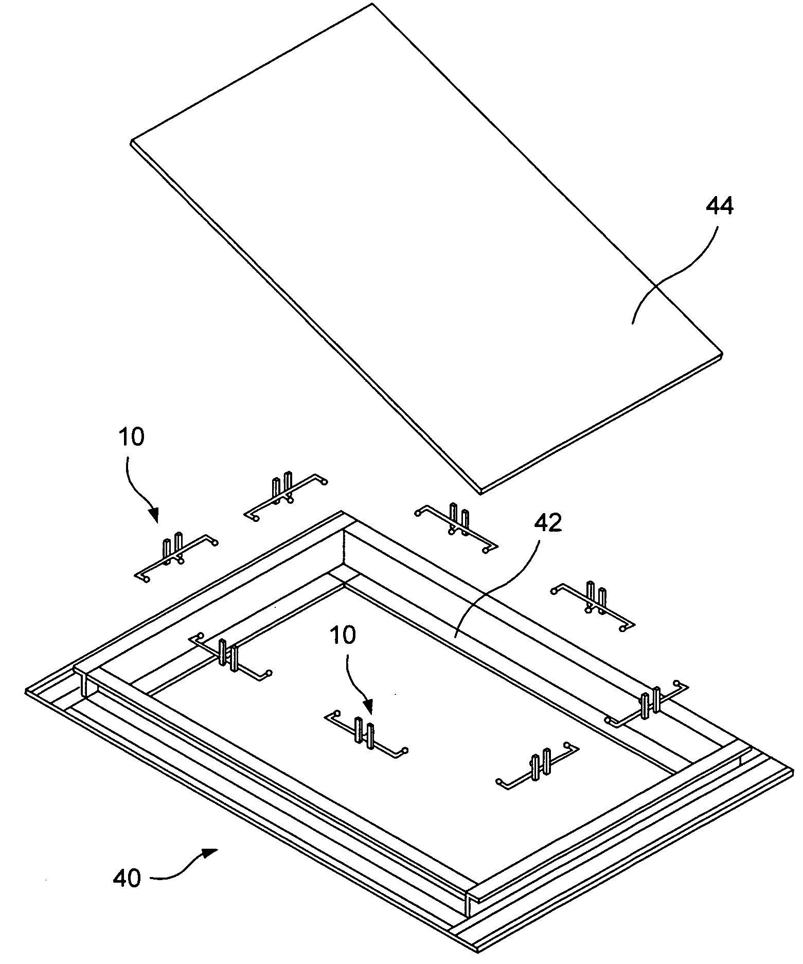
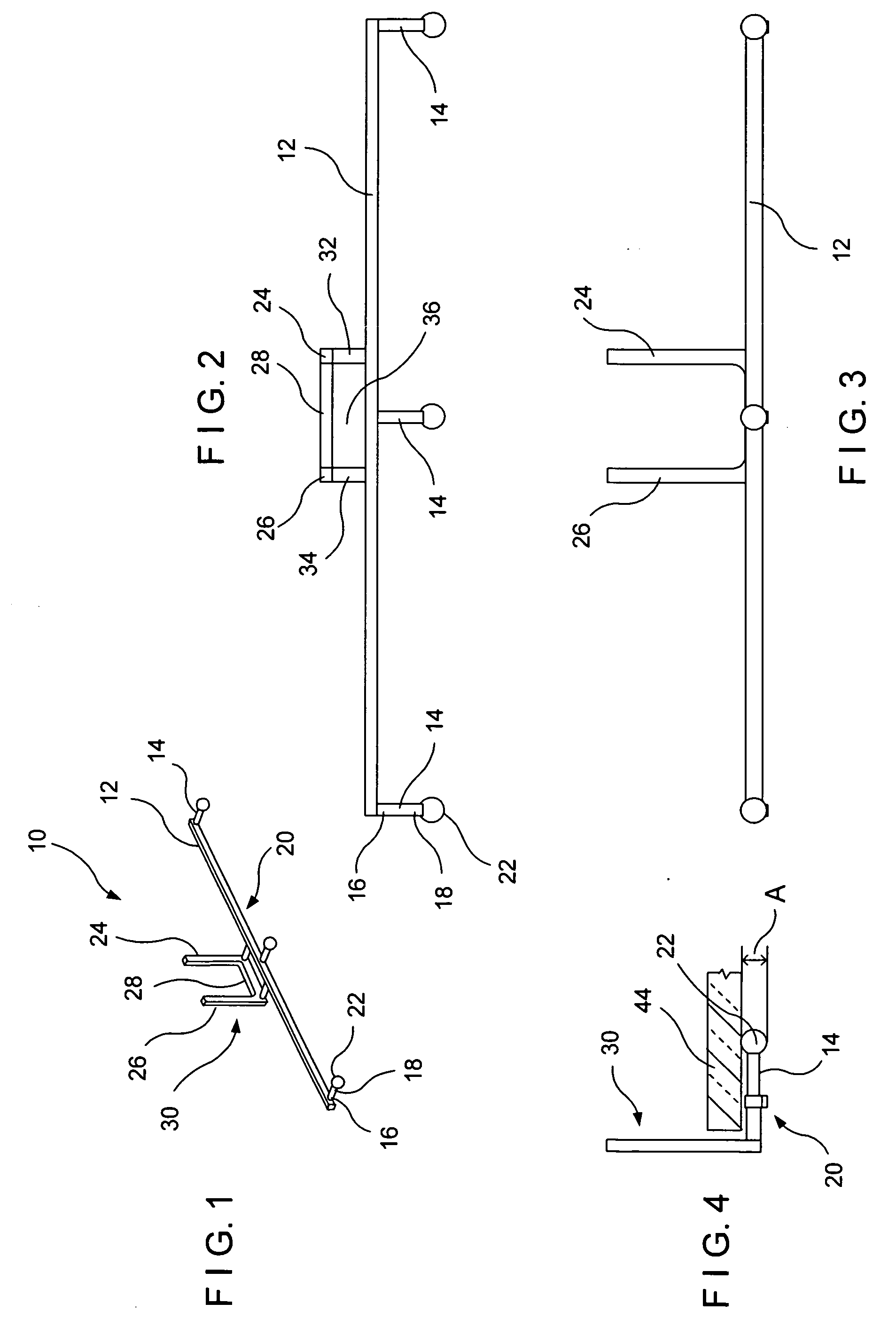
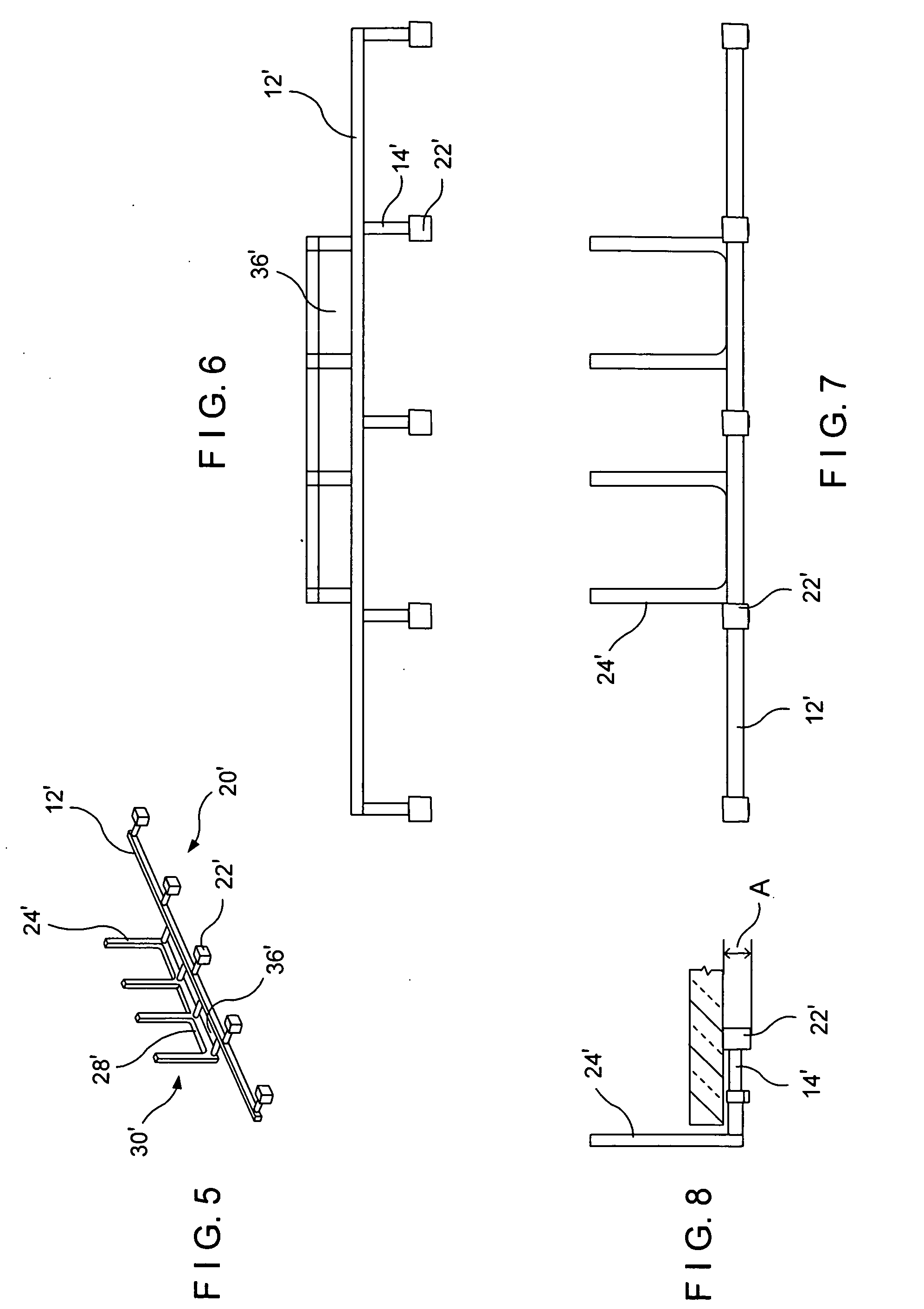
[0023]Referring now to the drawings in general and to FIGS. 1-4 in particular illustrating a preferred embodiment of the mounting device 10 of the invention. The device is formed by a base structure 20 and a restricting structure 30 positioned at an angle to each other. As to the base structure, an elongated base member 12 is disposed along a longitudinal axis of the device with a plurality of support members 14 extending outwardly from the base 12 in a spaced-apart relationship. A proximal end 16 of each support member is connected to the base 12 with an engaging formation 22 being provided at a distal free end 18 thereof. In the embodiment of FIG. 1, the base 12 and the support members 14 are formed having elongated straight-forward configuration. It should be noted however, that the base and support members having curved or any other conventional configuration are also contemplated. As illustrated in FIG. 1, the engaging formations 22 are shaped having a semi-spherical configurat...


PUM


Abstract

A mounting device is provided for holding a glazing panel against a supporting structure. The mounting device consists of a base having a plurality of spaced-apart support members. The base and support members defining a base plane. A restricting structure spaced from the base extends within a restricting plane transversely to the supporting plane. The glazing panel is disposed within the base plane and is supported by the base and support members.

Description

FIELD OF INVENTION[0001]The present invention relates in general to manufacturing and installation of glazing units, and more specifically it relates to mounting devices and method for installation and holding glazing units against a supporting structure.BACKGROUND OF THE INVENTION[0002]Glazing units such as glazed windows and doors used for wall and roof constructions must be capable of resisting both the static and dynamic loads as well as the impact loads to which they will be subjected. Principle wall and roof loads are created by high winds, and in the northern climates, by snow and ice. The evaluation of pressures exerted by wind on a building is complex, and local code requirements for wind forces can vary widely depending on the weather extremes expected in the area. The recommended design wind pressure on plane surfaces which are normal to the wind, increases with the height of the structure above ground level. Wind may also produce suction or pressure depending on configur...

Claims


Application Information

Patent Timeline
Patent Type & Authority Applications(United States)
IPC IPC(8): E06B3/968E06B3/58
CPCE06B3/5814E06B3/5409
Inventor SNYDER, BRANDONBEZUBIC, WILLIAM
Owner MI WINDOWS & DOORS
Why Eureka
Try Eureka