
Elastomeric spring-damper with integral stops

a technology of spring and stop, which is applied in the direction of shock absorbers, machine supports, transportation and packaging, etc., can solve the problems of increasing maintenance and cost, design and packaging problems, and increasing the number of parts, so as to reduce the width, reduce the width, and limit the longitudinal motion

Active Publication Date: 2013-07-09
TEXTRON INNOVATIONS
View PDF16 Cites 3 Cited by
  • Summary
  • Abstract
  • Description
  • Claims
  • Application Information

AI Technical Summary

Benefits of technology

[0007]There is a need for an improved spring-damper having reduced width and integral stops for limiting movement of an inner member carried within the spring-damper.
[0008]Therefore, it is an object of the present invention to provide an improved spring-damper having reduced width and integral stops for limiting movement of an inner member carried within the spring-damper.
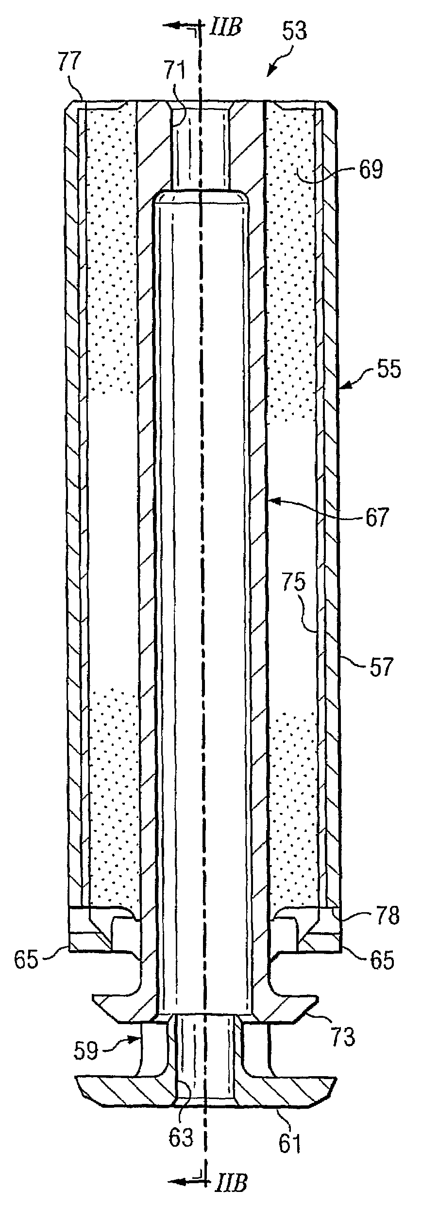
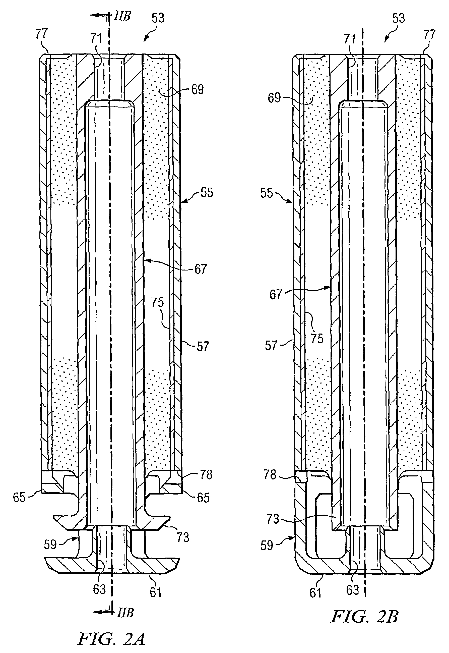
[0009]An elastomeric spring-damper has a one-piece tubular body having an integral cap. A tension stop flange is formed in the body near the cap portion, and a compression stop flange opposing the tension stop flange is formed on the cap portion. An inner member located within the body is coupled to the body with an annular elastomeric member, such that longitudinal motion of the inner member relative to the body is allowed through elastic deformation of the elastomeric member. An inner member stop flange is positioned between the compression stop flange and the tension stop flange to limit longitudinal motion of the inner member relative to the body.
[0010]The present invention provides for several advantages, including: (1) integral compression and / or tension stops; (2) reduced width; (3) reduced weight; (4) fewer components; and / or (5) improved ability for inspection of stop interfaces.

Problems solved by technology

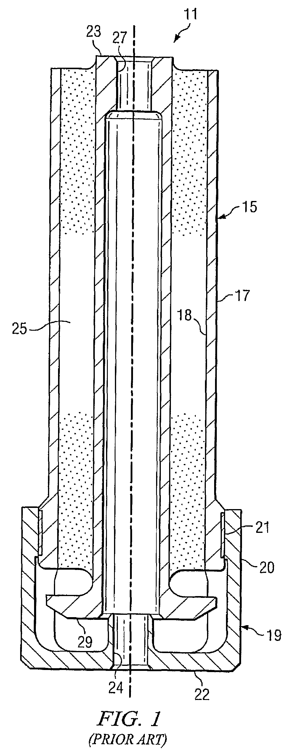
Various problems exist with spring-damper 11.
This greater diameter may present problems in the design and packaging of components connected to spring-damper 11.
Furthermore, the design provides a poor interface for stress translation across joint 21 and may lead to increased maintenance and cost due to a greater number of parts.

Method used


Image

  • Elastomeric spring-damper with integral stops
  • Elastomeric spring-damper with integral stops
  • Elastomeric spring-damper with integral stops

Examples


Embodiment Construction

[0019]The present invention provides an elastomeric spring, damper, or combination spring-damper assembly having integral compression and / or tension stops, reduced width, reduced weight, fewer components, and / or improved ability for inspection of stop interfaces. The assemblies have a rigid outer housing and a rigid inner member that can translate axially relative to the body, the housing and inner member each being adapted for connection to one of a pair of bodies that have relative motion. A resilient elastomeric member disposed between the outer housing and the inner member resists and damps the movement of the inner member, and this action resists and damps the relative motion of the attached bodies.

[0020]An assembly having an elastomeric member with a very low damping rate may be referred to as a spring, whereas an assembly having a very high damping rate may be referred to as a damper. An assembly having a damping rate between those of the springs and dampers may be referred t...


PUM

PropertyMeasurementUnit
elastic deformationaaaaaaaaaa
distanceaaaaaaaaaa
sizesaaaaaaaaaa

Abstract

An elastomeric spring-damper has a one-piece tubular body having an integral cap. A tension stop flange is formed in the body near the cap portion, and a compression stop flange opposing the tension stop flange is formed on the cap portion. An inner member located within the body is coupled to the body with an annular elastomeric member, such that longitudinal motion of the inner member relative to the body is allowed through elastic deformation of the elastomeric member. An inner member stop flange is positioned between the compression stop flange and the tension stop flange to limit longitudinal motion of the inner member relative to the body.

Description

TECHNICAL FIELD[0001]The present invention relates generally to elastomeric devices and relates particularly to elastomeric springs, dampers, and combination spring-dampers.DESCRIPTION OF THE PRIOR ART[0002]Elastomeric spring assemblies, damper assemblies, and combination spring-damper assemblies have been around for many years and come in various shapes and sizes. The assemblies typically have an outer housing and an inner member, the housing and inner member each being adapted for connection to one of a pair of components that have relative motion between them. A resilient elastomeric member disposed between the outer housing and the inner member provides a spring force opposing movement in the tension and compression directions and damps relative motion between the inner member and the housing. The spring force and damping force cooperate to resist and damp the relative motion between the components connected to the assembly.[0003]An assembly having an elastomeric member with a v...

Claims


Application Information

Patent Timeline
Patent Type & Authority Patents(United States)
IPC IPC(8): F16F7/00F16F1/44B60G11/22
CPCF16F1/3814F16F1/36B60G11/22F16F1/44F16M1/00
Inventor HALCOM, LANCER D.BOUQUILLON, BRIANHAYNIE, DAVID A.
Owner TEXTRON INNOVATIONS
Learn More