Liquid ejection head, liquid ejection apparatus and method of manufacturing liquid ejection head

a liquid ejection and liquid ejection technology, which is applied in the direction of printing, coating, metal material coating process, etc., can solve the problems of large stress generated repeatedly deformation or breaking and small cracks in the movable member, so as to increase the durability of the movable member

Inactive Publication Date: 2011-06-21
FUJIFILM CORP
View PDF7 Cites 21 Cited by
  • Summary
  • Abstract
  • Description
  • Claims
  • Application Information

AI Technical Summary

Benefits of technology

[0010]The present invention has been contrived in view of these circumstances, an object thereof being to provide a liquid ejection head, a liquid ejection apparatus, and a method of manufacturing a liquid ejection head, whereby the durability with respect to repeated stress of a moveable member which is arranged in the liquid ejection head in order to enhance ejection efficiency can be improved.

Problems solved by technology

However, the movable member provided in the liquid ejection head described in Japanese Patent Application Publication No. 2002-113871, Japanese Patent Application Publication No. 11-048483 and Japanese Patent Application Publication No. 2004-155203 is displaced by several micrometers to several ten micrometers every time a bubble is created by the heater, and therefore a large stress is generated repeatedly in the movable member and problems such as deformation or breaking of the movable member occur.
However, small cracks do occur in the movable member due to the repeated deformation, and no countermeasures are provided for preventing breakage of the movable member due to these small cracks.
However, countermeasures are not proposed for preventing the deformation of the movable member or the breaking of the movable member as a result of the repeated stress applied to the movable member during the ejection of liquid.

Method used


Image

  • Liquid ejection head, liquid ejection apparatus and method of manufacturing liquid ejection head
  • Liquid ejection head, liquid ejection apparatus and method of manufacturing liquid ejection head
  • Liquid ejection head, liquid ejection apparatus and method of manufacturing liquid ejection head

Examples


first modification example

[0135]Next, a first modification example of the present embodiment will be described. FIGS. 11A to 11G are diagram showing a schematic view of the respective steps of a method of manufacturing a movable member 120 which is bonded directly to a substrate 50, the fixing member 22 (see FIG. 1) for supporting the fixed end 120A of the movable member 120 being omitted from the composition. Similarly to FIGS. 8A to 8H and FIGS. 9A to 9L, steps other than those involved in manufacturing a substrate including a movable member are not shown and are omitted from the description.

[0136]The movable member 120 shown in FIG. 11G comprises: a fixed section 122 including a fixed end 120B which is fixed to a substrate 50; a raised section 124 having a shape which rises obliquely from the fixed section 122 in the direction of the nozzle (see FIG. 1); and a movable section 126 including a free end 120A which is arranged at a prescribed distance from the substrate 50.

[0137]FIGS. 11A to 11G show a schema...

second modification example

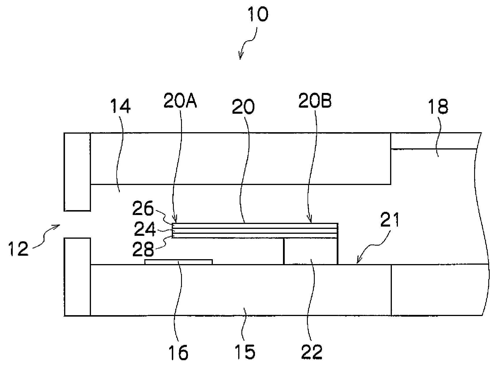
[0149]Next, a second modification example of the present embodiment will be described. FIG. 13 is a cross-sectional diagram showing the structure of a head 150 according to a second modification example. In FIG. 13, parts which are the same as or similar to FIG. 1 are labeled with the same reference numerals and further explanation thereof is omitted here.

[0150]The head 150 shown in FIG. 13 comprises a piezoelectric element 152 which serves as an ejection energy generation device (pressurization device), instead of the heater 16 of the head 10 in FIG. 1.

[0151]In other words, in this head 150, the fixed end 20B of a movable member 20 is bonded via a fixing member 22 to a diaphragm 154 which forms the bottom surface of the liquid chamber 14, on the surface corresponding to the inner side of the liquid chamber 14, and a piezoelectric element 152 is bonded to the diaphragm 154 on the surface corresponding to the outside of the liquid chamber 14, at a position corresponding to the free e...

third modification example

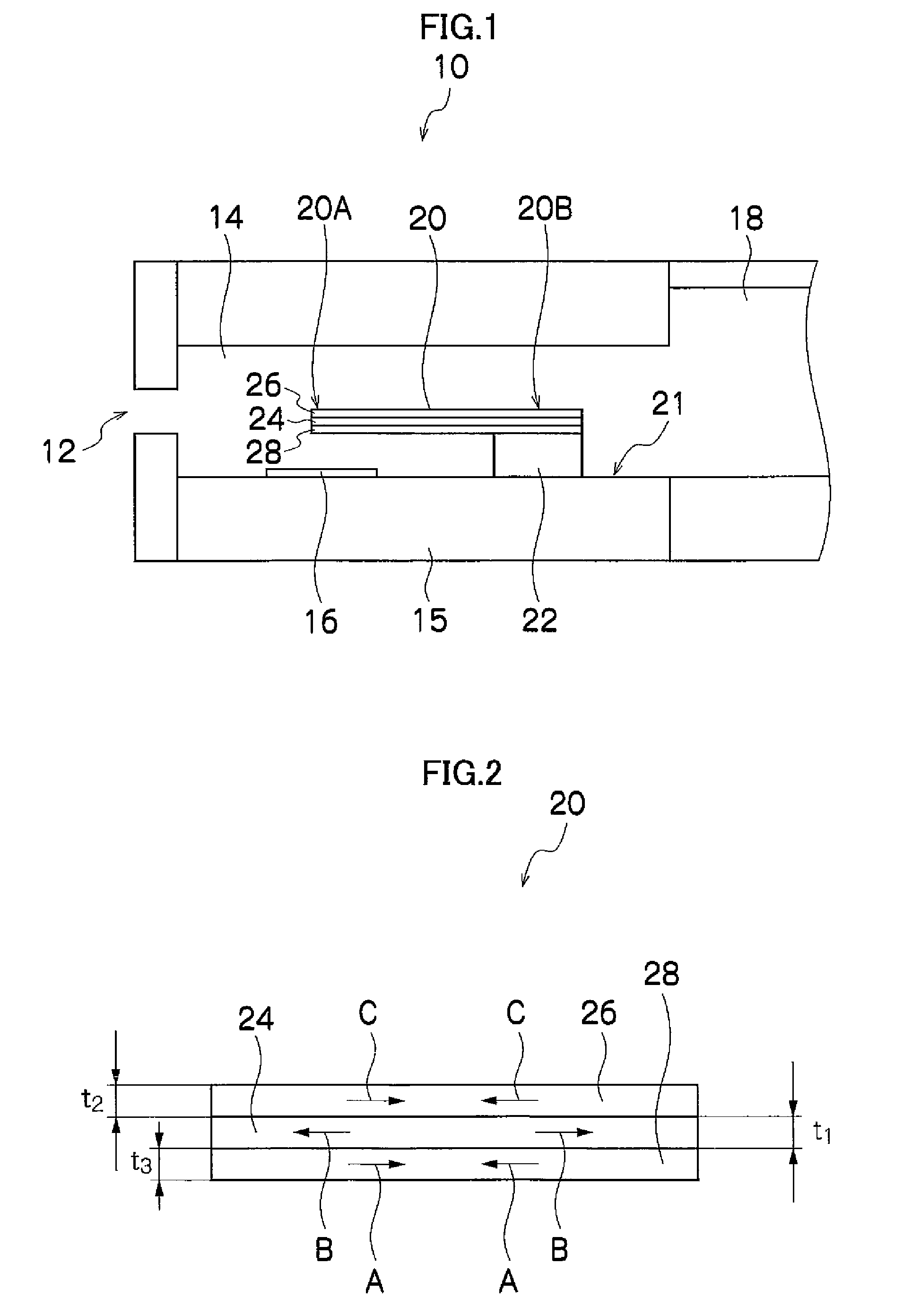
[0160]Next, a third modification example of the present embodiment will be described with reference to FIGS. 14A to 14C. The movable member 20 (120) described above has a structure in which the first layer 24 is exposed on the four side faces (end faces) (See FIG. 1, for example). In the structure in which the first layer 24 having the tensile stress is exposed, cracks are liable to enter into the first layer 24 in the exposed portion. Therefore, the exposed portion of the first layer 24 may be covered by a material having compressive stress, as shown in FIGS. 14A to 14C, thereby preventing cracks from occurring in the first layer 24.

[0161]FIG. 14A is a cross-sectional diagram of a head 200 according to the third modification example, FIG. 14B is an enlarged cross-sectional diagram of the movable member 220 shown in FIG. 14A, and FIG. 14C is a plan diagram showing the movable member 220 shown in FIG. 14B as viewed from above.

[0162]As shown in FIG. 14A, the head 200 has the same stru...


PUM

PropertyMeasurementUnit
thicknessaaaaaaaaaa
lengthaaaaaaaaaa
widthaaaaaaaaaa

Abstract

A liquid ejection head includes: an ejection port through which liquid is ejected; a liquid chamber which is connected to the ejection port, the liquid chamber being filled with the liquid; a pressurization device which is arranged on a wall of the liquid chamber, the pressurization device pressurizing the liquid in the liquid chamber; and a movable member which has a free end on a side of the ejection port and a fixed end on a side opposite to the ejection port, the free end being arranged at a prescribed distance from the wall of the liquid chamber so as to face the wall of the liquid chamber, the movable member including a first layer that is an internal layer, and second and third layers that are respectively arranged on both surfaces of the first layer, the second and third layers having a stress lower than the first layer.

Description

BACKGROUND OF THE INVENTION[0001]1. Field of the Invention[0002]The present invention relates to a liquid ejection head, a liquid ejection apparatus and a method of manufacturing a liquid ejection head, and more particularly, to a structure for improving the durability of the liquid ejection head and a method of manufacturing the liquid ejection head having the above-described structure.[0003]2. Description of the Related Art[0004]In general, an inkjet recording apparatus which forms a desired image by ejecting ink droplets from a liquid ejection head onto a recording medium has been widely used as a generic image forming apparatus. In inkjet recording apparatuses, various innovations have been applied to the structure and shape of the flow channels inside the liquid ejection head in order to achieve high-speed ejection by improving the ejection efficiency and improving the refilling efficiency.[0005]Japanese Patent Application Publication No. 2002-113871, Japanese Patent Applicatio...

Claims


Application Information

Patent Timeline
Patent Type & Authority Patents(United States)
IPC IPC(8): B41J2/04
CPCB41J2/14048B41J2/1604B41J2/1623B41J2/1626B41J2/1642B41J2/1646B41J2/1625B41J2002/14379
Inventor YOKOUCHI, TSUTOMU
Owner FUJIFILM CORP
Why Eureka
Try Eureka