
Floor drain

a technology for drains and floors, applied in the field of floor drains, can solve problems such as multi-step adjustment process, and achieve the effect of quick and easy adjustmen

Inactive Publication Date: 2011-06-21
GRAYBEAL K MICHAEL
View PDF13 Cites 44 Cited by
  • Summary
  • Abstract
  • Description
  • Claims
  • Application Information

AI Technical Summary

Benefits of technology

[0009]The general object of this invention is to provide an improved floor drain. A more particular object is to provide a floor drain with minimal parts that enables the height and pitch of the grate or cover to be adjusted quickly and easily with the grate or cover in place.
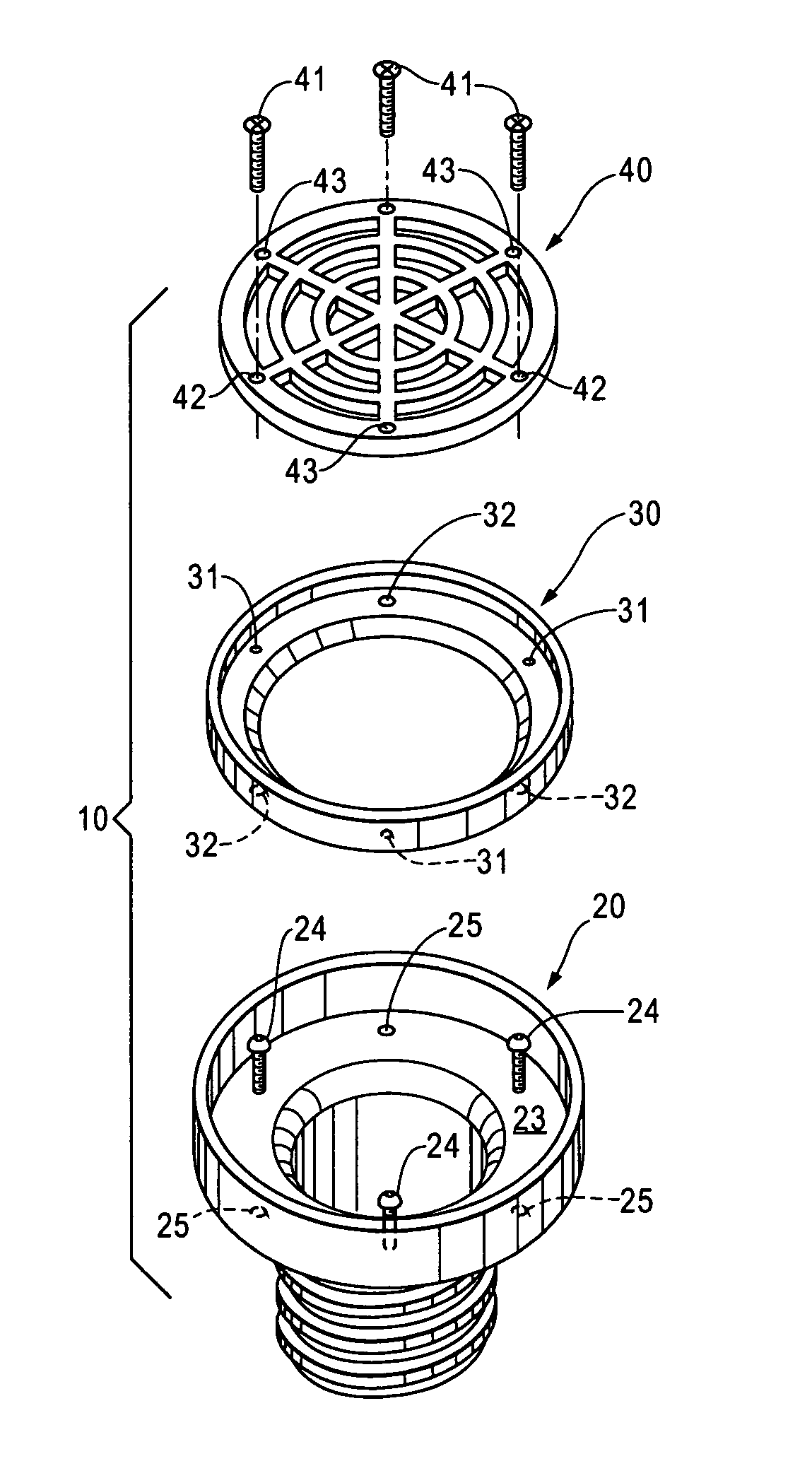
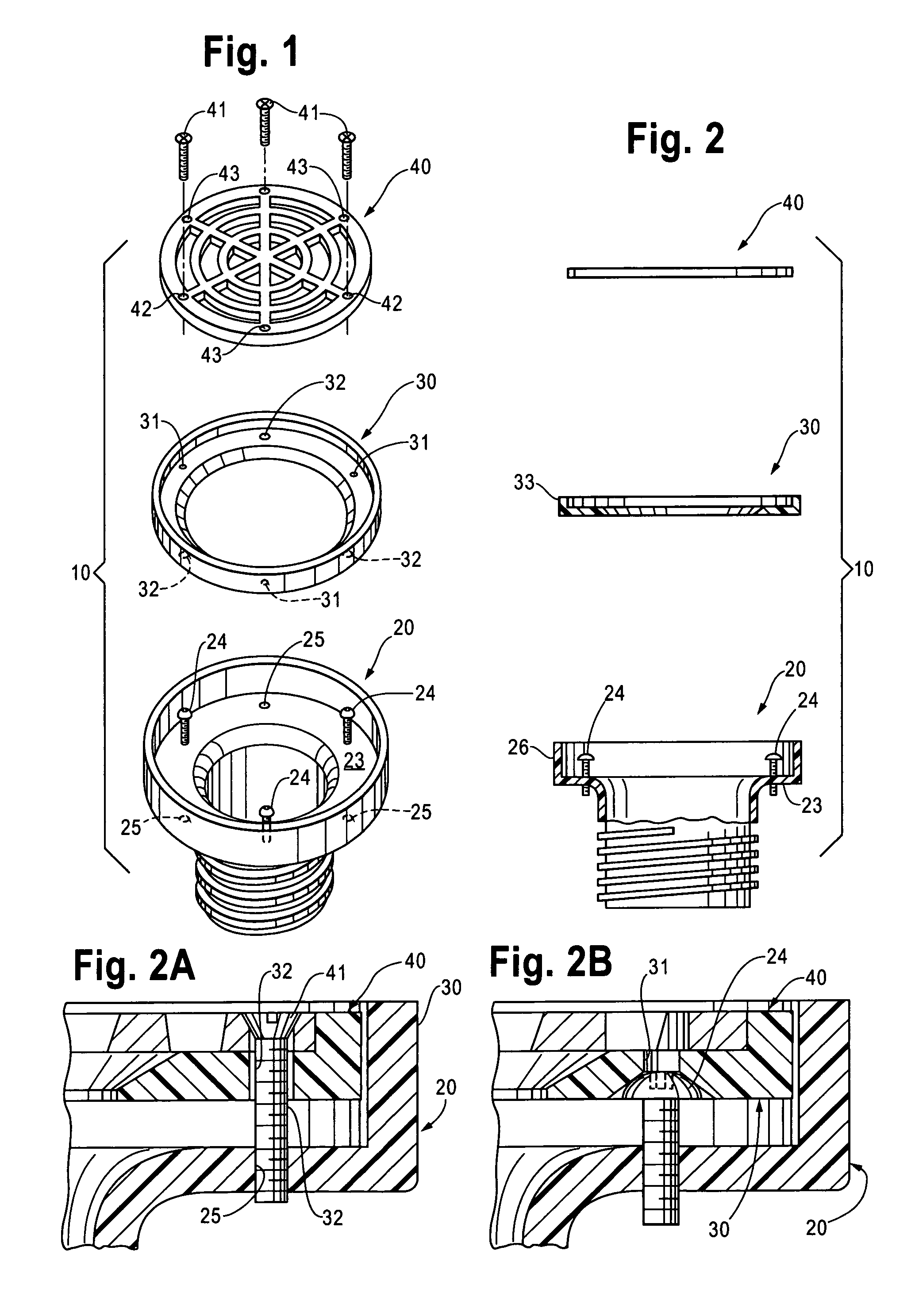
[0011]The floor drain of this invention has only three major parts. It enables the height and pitch of the grate or cover to be adjusted quickly and easily in one step with the grate or cover in place.

Problems solved by technology

First, they both contain numerous parts.
Second, they both require the grate or cover to be removed for adjustment of height and pitch.
Third, they both require a multiple-step adjustment process.

Method used


Image

  • Floor drain
  • Floor drain

Examples


Embodiment Construction

[0014]This invention is best understood by reference to the drawings. Referring to FIGS. 1 and 2, the preferred embodiment of the floor drain 10 of this invention comprises a flanged cylindrical body 20, a ring 30, and a grate or cover 40. Grates and covers are similar in construction with the obvious difference that a grate contains multiple openings for the passage of water. For simplicity, only a grate is discussed below. However, it is understood that covers are included. The floor drain fits into a vertical pipe that may or may not include a fitting (not shown) that is below floor level. Each of the components of the floor drain is discussed in detail below.

[0015]The flanged cylindrical body 20 is the component of the floor drain that directly communicates with the vertical pipe or fitting. The cylinder (cylindrical portion) 21 of the body has a vertical axis and fits within the vertical pipe or fitting. A watertight seal is formed between the outer surface of the body and the ...


PUM

PropertyMeasurementUnit
diameteraaaaaaaaaa
perimeteraaaaaaaaaa
heightaaaaaaaaaa

Abstract

A floor drain communicates with a vertical floor drain pipe. The floor drain has a flanged cylindrical body that fits within the vertical pipe or fitting, a ring that overlaps and is spaced above the flange, and a grate or cover that fits upon the upper surface of the ring. The ring is supported by elevating screws that pass through the flange of the body. Adjustment of the elevating screws enable the height and pitch of the ring and grate or cover to be quickly and easily adjusted.

Description

CROSS-REFERENCE TO RELATED APPLICATION[0001]This application claims the benefit of U.S. Provisional Application Ser. No. 61 / 209,874, Mar. 11, 2009.FIELD OF THE INVENTION[0002]This invention relates to plumbing. More particularly, this invention relates to floor drains and cleanouts.BACKGROUND OF THE INVENTION[0003]Buildings are commonly constructed with concrete floors having openings that communicate with a sewer system. A floor opening is commonly referred to as a floor drain when a grate (also known as a strainer) is placed over the opening and is commonly referred to as a cleanout when a solid cover (also known as a plug) is placed over the opening. The primary purpose of a floor drain is to allow water on the floor to escape and the primary purpose of a cleanout is to provide access to the sewer system for cleaning. The term “floor drain” is used herein to refer to both types of floor openings. The parts that typically make up a floor drain consist of a grate (or cover) and a c...

Claims


Application Information

Patent Timeline
Patent Type & Authority Patents(United States)
IPC IPC(8): E03F5/04
CPCE03F5/04E03F2005/0413
Inventor GRAYBEAL, K. MICHAEL
Owner GRAYBEAL K MICHAEL
Learn More