Method and device for producing a fuselage cell of an airplane

a technology of fuselage cell and fuselage plate, which is applied in the direction of aircraft assembly, metal-working apparatus, vehicle components, etc., can solve the problems of tolerance compensation and the inability to completely avoid the joint area for manufacturing reasons

Active Publication Date: 2011-06-28
AIRBUS OPERATIONS GMBH
View PDF16 Cites 26 Cited by
  • Summary
  • Abstract
  • Description
  • Claims
  • Application Information

AI Technical Summary

Benefits of technology

[0010]Circularly attaching the at least two shell components to a ready-made cockpit section and / or to a ready-made rear section results in an efficient production, wherein at the same time tolerance problems between the large components are avoided.
[0025]For being able to produce even longer fuselage sections further side shells as well as upper and lower shells can be connected to the shell components which are already attached to the ready-made cockpit section and / or rear section. Alternatively it is possible to use longer shell components which each by itself already comprises the required length extent for forming the entire fuselage cell.
[0043]Due to the simultaneous production of in total at least four cross-seams between the sections the production efficiency can be increased considerably whereas on the other hand also the area need of the “central” site rises. In case of a cockpit section, a wing box section and a rear section without intermediate sections the number of cross-seams reduces to the number of “three”. The number of cross-seams rises accordingly if intermediate sections are inserted between the cockpit section and the central wing box section and / or between the central wing box section and the rear section.

Problems solved by technology

During integration of the fuselage sections to an entire fuselage cell, the problem of tolerance compensation between the fuselage sections to be joined arises.
Particularly with fuselage sections having big diameters of up to 10 meters tolerance deviations, i.e., particularly deviations between a desired and an actual cross-sectional geometry of the fuselage section in the joint area cannot be completely avoided for manufacturing reasons.

Method used


Image

  • Method and device for producing a fuselage cell of an airplane
  • Method and device for producing a fuselage cell of an airplane
  • Method and device for producing a fuselage cell of an airplane

Examples


Embodiment Construction

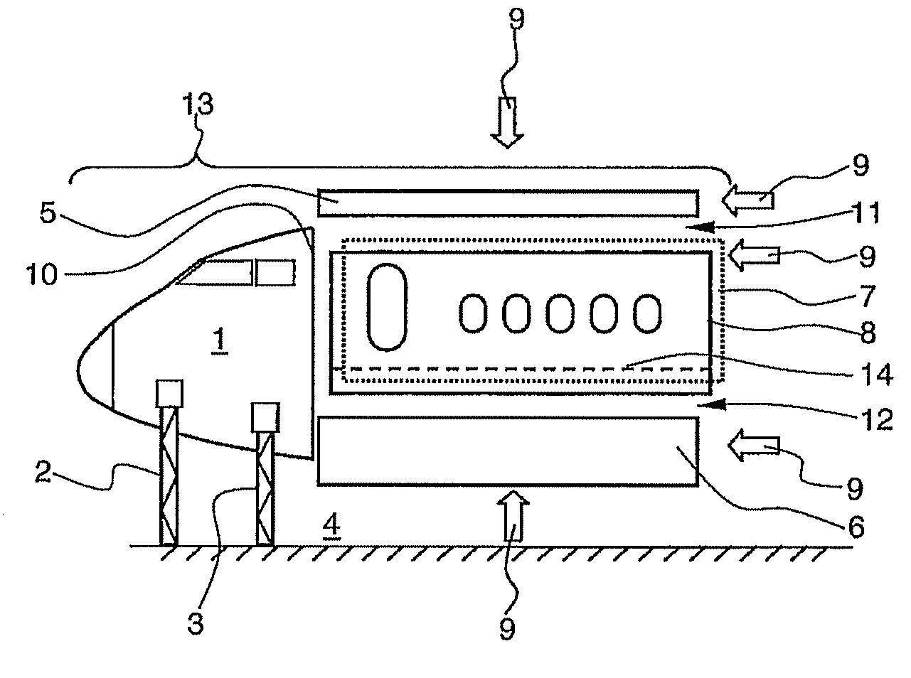
[0051]FIG. 1 shows an illustration of the procedure of the method during the production of a front fuselage section of a fuselage cell of an airplane.

[0052]An entirely pre-fabricated and already completed cockpit section 1 is firstly received by two retaining devices 2, 3 in a site 4 (base area of the site) and is positioned and / or aligned. Two further retaining devices are added to the retaining devices 2, 3 which are arranged behind these and are therefore not shown in the illustration of FIG. 1. The cockpit section 1 is received between these altogether four retaining devices and can be positioned in all three directions in space of the site 4. Subsequently a plurality of shell components (shells or fuselage cells) that is an upper shell 5, a lower shell 6 as well as two side shells 7, 8 are each positioned closer to the cockpit section 1 for instance in the direction of the arrows 9 by means of the positioning devices not shown in the illustration of FIG. 1 and are connected to ...


PUM

PropertyMeasurementUnit
diametersaaaaaaaaaa
lengthaaaaaaaaaa
areaaaaaaaaaaa

Abstract

The invention relates to a method for the economic production of entire fuselage cells of airplanes and to a site for carrying out the method. Differing from the conventional sectional assembly according to the invention separate shells (shell components) are attached to a substantially completed cockpit section and / or rear section. At this the half shell construction and the four shell construction as well as a combination hereof can be applied. Alternatively, the cockpit section and the rear section as well as the central wing box section can be aligned and positioned to each other in a site forming gaps in longitudinal direction. Subsequently, the shell components as well as the floor framework sections are adjusted circularly revolving between the sections and are ideally simultaneously connected to these by means of at least four cross-seams and a plurality of longitudinal seams.

Description

CROSS-REFERENCE TO RELATED APPLICATIONS[0001]This application is a continuation of PCT International Application No. PCT / EP2008 / 057850 filed Jun. 20, 2008, which claims the benefit of U.S. Provisional Application No. 60 / 936,846, filed Jun. 22, 2007 and German Patent Application No. 10 2007 028 918.0, filed Jun. 22, 2007, the entire disclosures of which are herein incorporated by reference.FIELD OF THE INVENTION[0002]The invention relates to a method for producing a fuselage cell of an airplane with an at least partially pre-fabricated cockpit section and with an at least partially pre-fabricated rear section.[0003]Furthermore, the invention relates to a site for carrying out the method.[0004]Nowadays, in aircraft construction the sectional construction for producing fuselage cells for aircrafts is widely used. According to this fuselage shells, particularly two side shells, an upper and a lower shell as well as a floor framework are joined to a fuselage section (“barrel”) while form...

Claims


Application Information

Patent Timeline
Patent Type & Authority Patents(United States)
IPC IPC(8): B21D53/88B25B27/14
CPCB64F5/0009Y10T29/49622Y10T29/53961B64F5/10
Inventor FRAUEN, HOLGERGNAUCK, TOMASKLEMKOW, EIKE
Owner AIRBUS OPERATIONS GMBH
Why Eureka
Try Eureka