Cooling storage cabinet

a storage cabinet and cooling technology, applied in the field of cooling storage cabinets, can solve the problems of shortening the life of the starter, and achieve the effect of ensuring the start-up of the compressor

Inactive Publication Date: 2011-06-28
HOSHIZAKI ELECTRIC CO LTD
View PDF5 Cites 0 Cited by
  • Summary
  • Abstract
  • Description
  • Claims
  • Application Information

AI Technical Summary

Benefits of technology

[0015]In accordance with the present invention, voltage applied to the compressor can be ensured and start-up of the compressor can be ensured even in the event of lower power-source voltage.

Problems solved by technology

This creates a problem of shortening the life of the starter.

Method used


Image

  • Cooling storage cabinet
  • Cooling storage cabinet
  • Cooling storage cabinet

Examples


embodiment

[0020]An embodiment in accordance with the present invention will be explained with reference to FIGS. 1 through 4.

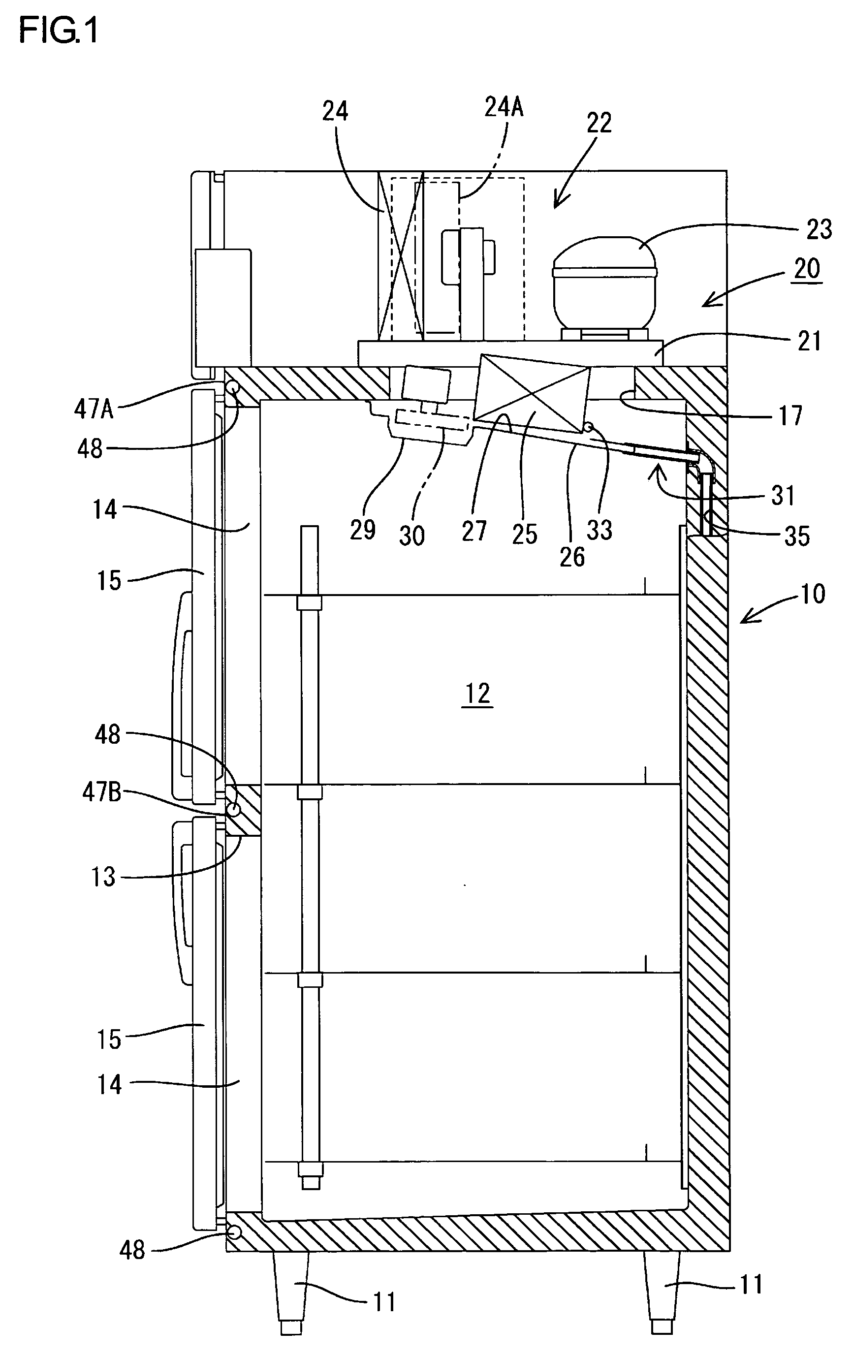
[0021]Illustrated in this embodiment is a case where the present invention is adopted to an upright refrigerator for commercial use. First, a general structure of the refrigerator will be explained with reference to FIG. 1. A refrigerator body 10 is configured by a vertically elongated heat-insulating box body having an opening in the front side thereof. The refrigerator body 10 is supported by legs 11. The legs 11 are provided in four corners of a bottom face of the refrigerator body 10. The inside of the refrigerator body 10 is defined as a storage compartment 12. The front opening of the storage compartment 12 is separated with a separation frame 13 into an upper and a lower openings 14. Each of the openings 14 has a heat-insulating door 15 attached thereto. The heat-insulating doors 15 are pivotable so as to open and close the respective openings 14.

[0022]A window h...


PUM


Abstract

One aspect of the present invention includes a cooling storage cabinet having a compressor that is included in a freezing device, a heater that is connected in parallel with the compressor to a power source, a switch that controls supply of current to the compressor, and a control unit that stops supply of current to the heater during a predetermined time after the switch operates start-up of the compressor.

Description

TECHNICAL FIELD[0001]The present invention relates to a cooling storage cabinet. More specifically, the present invention relates to improvement of start-up performance of a compressor at a time of starting a cooling operation.BACKGROUND ART[0002]A known refrigerator for commercial use (for example, see Patent Document 1) has a function to perform a defrosting operation during intervals of a cooling operation. Specifically, an evaporator and an evaporator fan are equipped in a storage compartment. The evaporator is connected to a freezing device including a compressor. On the other hand, the evaporator is equipped with a defrost heater. At a time of the cooling operation, the compressor and the evaporator fan are driven to generate cool air around the evaporator. The cool air is circularly supplied to the storage compartment to cool the storage compartment. On the other hand, the defrosting operation is performed by supplying current to the defrost heater in a state where the compre...

Claims


Application Information

Patent Timeline
Patent Type & Authority Patents(United States)
IPC IPC(8): G05D23/32F25B49/00F25D21/00F25D21/06
CPCF25B49/025F25D21/04F25B2500/26F25B2600/0251F25D2600/06F25D2400/02F25D2600/02
Inventor HOSAKA, SEIKI
Owner HOSHIZAKI ELECTRIC CO LTD
Why Eureka
Try Eureka