Method for controlling a driving dynamics control device, and driving dynamics control device

a technology of driving dynamics and control device, which is applied in the direction of braking system, electronic commutator, braking components, etc., can solve the problems of high energy consumption, high cost, and large or very powerful electric motors, and achieve the sum of the torques required to move the pump elements. likely to be high, and the effect of increasing the number of times

Pending Publication Date: 2021-01-21
ROBERT BOSCH GMBH
View PDF22 Cites 0 Cited by
  • Summary
  • Abstract
  • Description
  • Claims
  • Application Information

AI Technical Summary

Benefits of technology

[0006]Embodiments of the present invention may advantageously make it possible to provide a method for controlling a driving dynamics control device, or to provide a driving dynamics control device by which or in which a start-up of an electric motor is ensured at all times even when an electric motor is used that is not very powerful.

Problems solved by technology

The electric motor is consequently quite large or very powerful, and thus expensive.
In addition, the energy consumption then is usually lower as a result.
The rotor is adjusted to the ideal position, i.e., stopped in the ideal position or moved to the ideal position, after the motor has stopped moving only when it has to be assumed that the pump must supply brake fluid or has to start up against a high pressure, which means that the sum of the torques required to move the pump elements is likely going to be high, with the possible result that the electric motor may be difficult or slow to start up.
The rotor is adjusted or moved to the ideal position only if the likelihood is high that the pump has to supply brake fluid against a high pressure and the electric motor may thus possibly start up only with difficulty or slowly.
Typically, an unnecessary adjustment or movement of the rotor in the ideal position or to the ideal position thus takes place even more rarely.

Method used


Image

  • Method for controlling a driving dynamics control device, and driving dynamics control device
  • Method for controlling a driving dynamics control device, and driving dynamics control device
  • Method for controlling a driving dynamics control device, and driving dynamics control device

Examples


Embodiment Construction

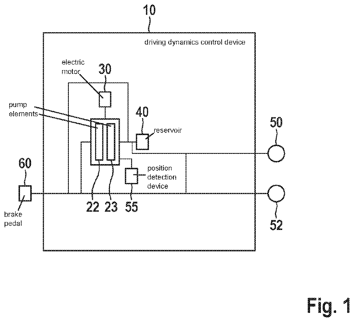
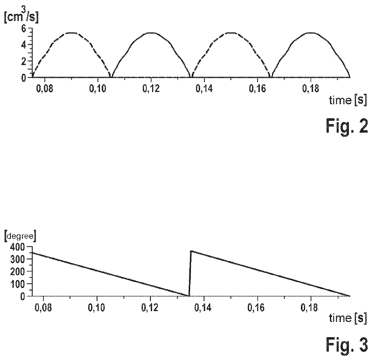
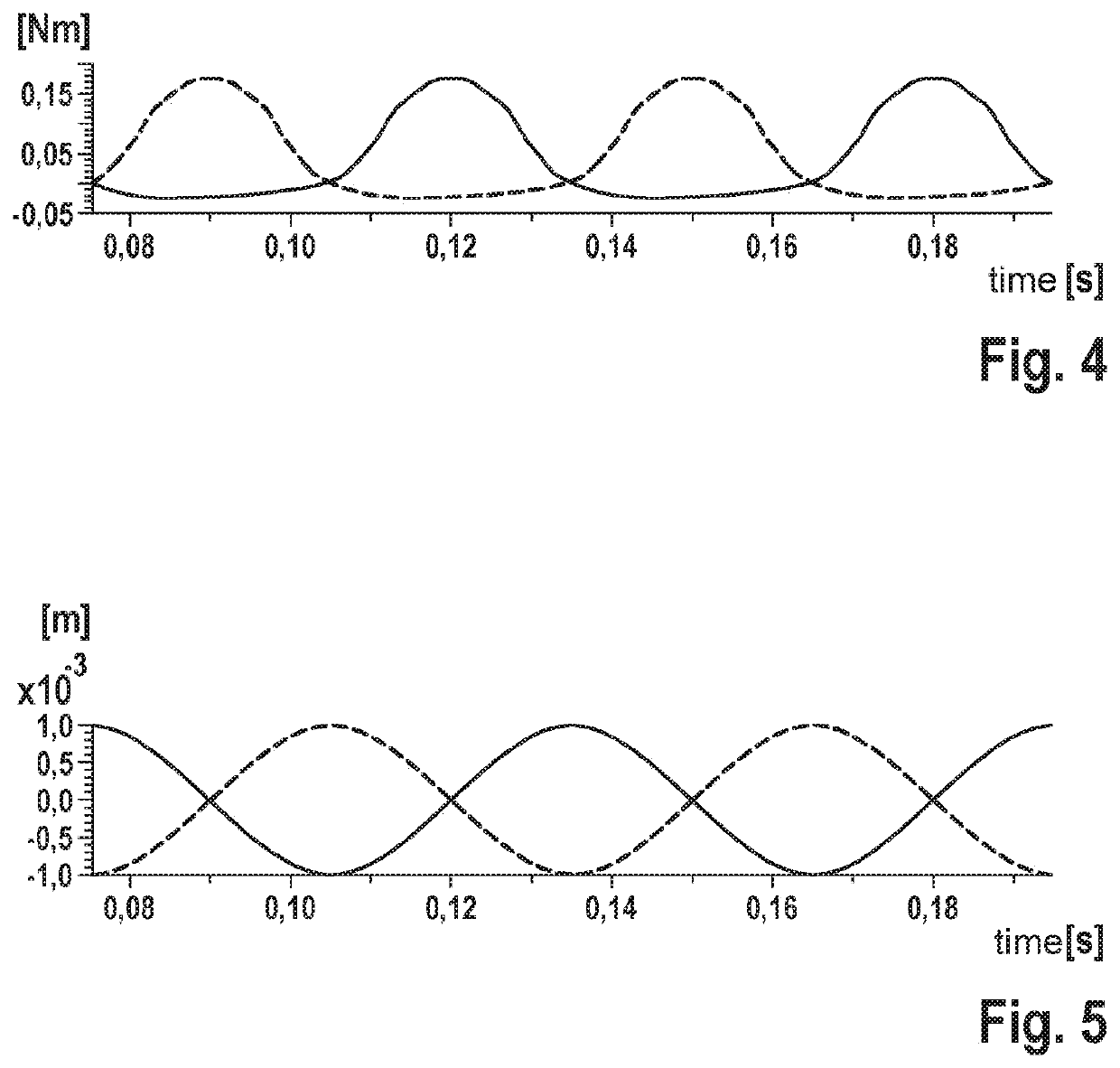
[0034]FIG. 1 shows a schematic view of a specific embodiment of the driving dynamics control device 10 according to the present invention. FIG. 2 shows a diagram of the supply flow of first pump element 22 and second pump element 23 of driving dynamics control device 10 of FIG. 1 as a function of time. FIG. 3 shows a diagram of an angle of the rotor relative to the stator of electric motor 30 of driving dynamics control device 10 of FIG. 1 as a function of time. FIG. 4 shows a diagram of the torques of first pump element 22 and second pump element 23 of driving dynamics control device 10 of FIG. 1 as a function of time. FIG. 5 shows a diagram of the eccentric travel of first pump element 22 and second pump element 23 of driving dynamics control device 10 of FIG. 1 as a function of time.

[0035]A multitude of valves has been omitted in FIG. 1 for reasons of clarity.

[0036]In FIG. 2, the y-axis indicates the supplied brake fluid quantity in cm3 / sec. In FIG. 3, the y-axis indicates the an...


PUM


Abstract

A method is provided for controlling a driving dynamics control unit for influencing the braking of wheels of a motor vehicle. The driving dynamics control device having a pump, which includes at least two pump elements for the supply of brake fluid, and an electric motor, which includes a rotor and a stator for driving the pump elements. The method includes the following steps: detecting the position of the rotor relative to the stator, and adjusting an ideal position of the rotor relative to the stator, the sum of the torques for moving the pump elements lying below a predefined torque limit value, in particular being minimal, in the ideal position.

Description

FIELD[0001]The present invention relates to a method for controlling a driving dynamics control device and to a driving dynamics control device.BACKGROUND INFORMATION[0002]In driving dynamics control devices such as ESP systems (systems for an electronic stability control) in motor vehicles, the active displacement or supply of brake fluid for an active pressure buildup in the brake fluid or for an evacuation of a low-pressure accumulator chamber for the brake fluid is carried out with the aid of an electrically operated return pump.[0003]When configuring a rotational speed / torque characteristic curve for this electric motor having a rotor and a stator, particular attention should be paid to the ABS (anti-lock braking system) high-pressure configuration point in which the electrically driven return pump has to be capable of starting up against very high pressures or maximally possible pressures of the brake fluid. The electric motor for driving the pump or the return pump must start...

Claims


Application Information

Patent Timeline
Patent Type & Authority Applications(United States)
IPC IPC(8): B60T8/1755B60T13/20B60T7/12B60T13/66B60T17/22H02P6/16
CPCB60T8/1755B60T13/20B60T7/12B60T2270/306B60T17/221H02P6/16B60T2270/10B60T13/662B60T8/4022B60T8/405B60T8/4872
Inventor BODMANN, JOCHENSCHMIDTLEIN, ANDREASEMDE, CHRISTOPH
Owner ROBERT BOSCH GMBH
Why Eureka
Try Eureka