Plating apparatus

a technology of plating apparatus and plating rate, which is applied in the direction of electrolysis components, instruments, magnetic property measurements, etc., can solve the problems of non-uniform composition, abnormal deposition, and the like of the magnetostrictive film 108, and achieve uniform composition and thickness, prevent abnormal deposition, and short time

Inactive Publication Date: 2011-06-28
HONDA MOTOR CO LTD
View PDF19 Cites 1 Cited by
  • Summary
  • Abstract
  • Description
  • Claims
  • Application Information

AI Technical Summary

Benefits of technology

[0008]Thus, in order to eliminate the above described disadvantages, it is possible to increase the plating rate in such a manner that there is further provided a propeller (not shown) on the bottom surface of the plating tank 102, and that the plating liquid 103 is stirred by rotating the propeller so that the Ni ion concentration and the Fe ion concentration on the surface of the shaft-shaped member 104 are kept uniform. However, when the stirring intensity is low, only the plating liquid 103 near the bottom surface of the plating tank 102 is stirred, and the plating liquid 103 on the surface of the shaft-shaped member 104 is not sufficiently stirred. Thereby, the Ni-ion concentration and the Fe ion concentration in the plating liquid 103 on the surface of the shaft-shaped member 104 are made non-uniform on the upper and lower sides of the shaft-shaped member 104. This results in disadvantages that the Fe / Ni composition ratio in the magnetostrictive film 108 formed on the surface of the shaft-shaped member 104 is made non-uniform in the vertical direction of the magnetostrictive film 108, and that the thickness of the magnetostrictive film 108 is made non-uniform in the vertical direction of the magnetostrictive film 108. Further, since the plating liquid 103 is not sufficiently stirred, the Ni ion concentration and the Fe ion concentration in the plating liquid 103 are lowered on the surface of the shaft-shaped member 104. This results in a disadvantage that abnormal deposition is caused in the magnetostrictive film 108.

Problems solved by technology

This results in a disadvantage that the plating rate cannot be increased.
This results in a disadvantage that there occur abnormal deposition in which the composition, and the like, of the magnetostrictive film 108 is made non-uniform.

Method used


Image

  • Plating apparatus
  • Plating apparatus
  • Plating apparatus

Examples


Embodiment Construction

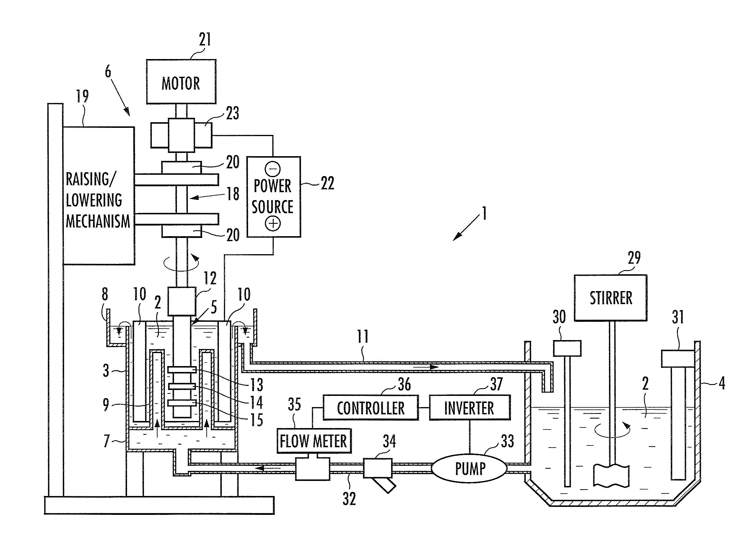
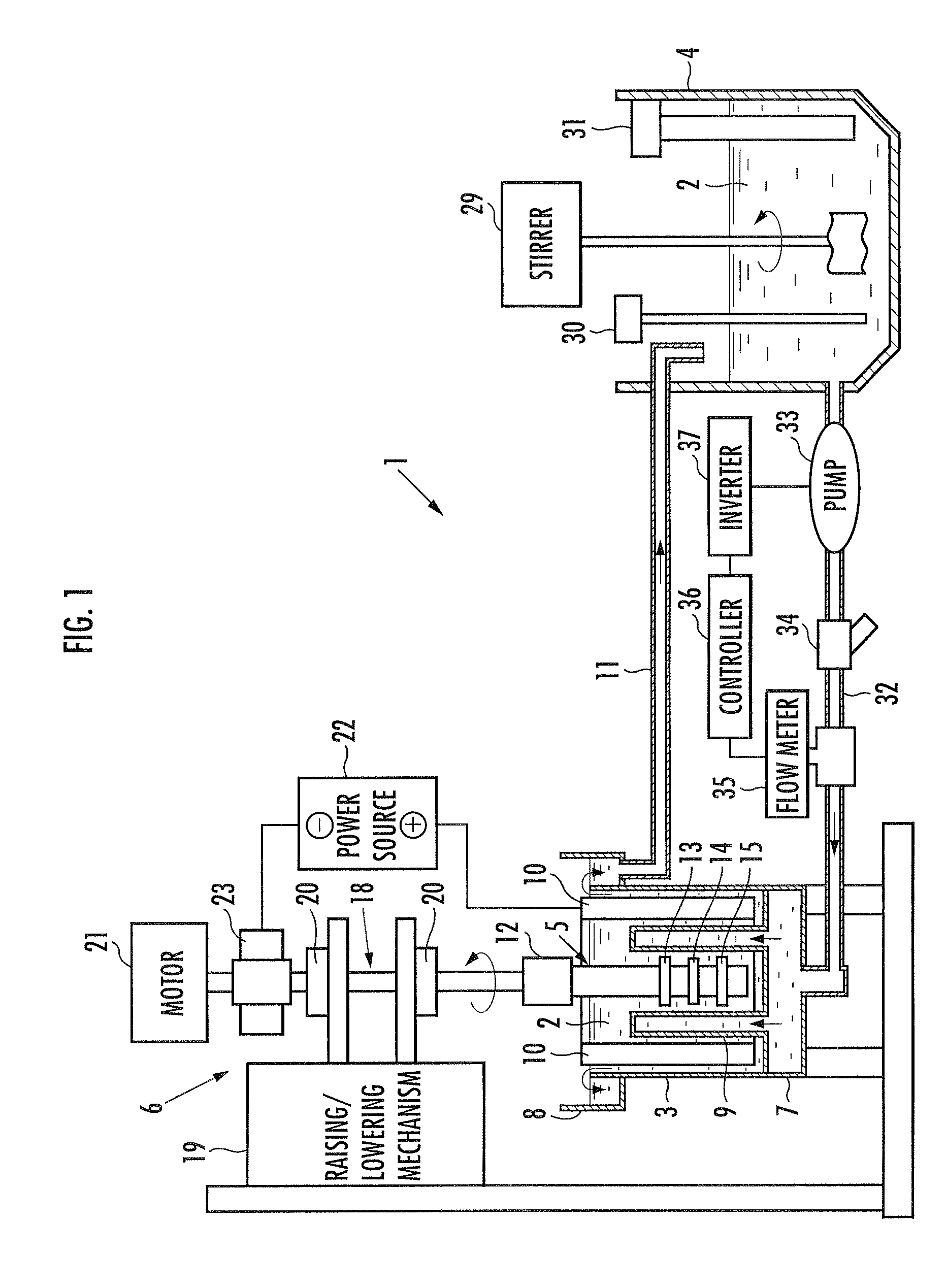
[0021]In the following, embodiments according to the present invention will be described in more detail with reference to the accompanying drawings. FIG. 1 is an explanatory front view showing a configuration example of a plating apparatus according to the present embodiment.

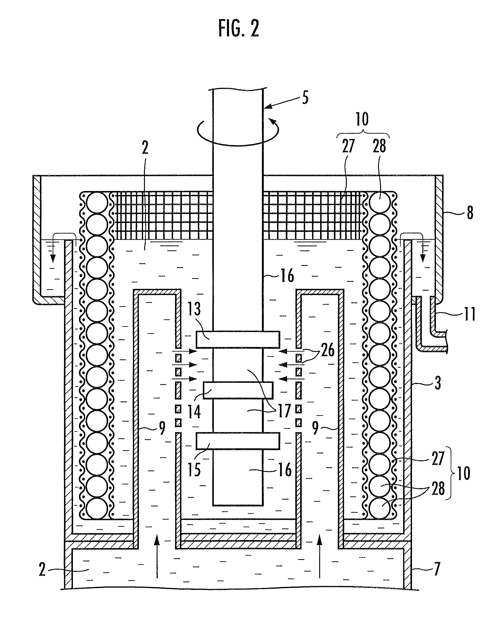
[0022]FIG. 2 is an explanatory sectional view showing an internal configuration of a plating tank of the plating apparatus according to the present embodiment shown in FIG. 1. FIG. 3 is an explanatory plan view showing an internal configuration of the plating tank of the plating apparatus according to the present embodiment shown in FIG. 1. FIG. 4 is an explanatory perspective view showing a plating liquid discharge nozzle of the plating apparatus according to the present embodiment shown in FIG. 1. Note that in FIG. 4, the portion surrounded by the circle A is shown on an enlarged scale.

[0023]The plating apparatus 1 includes a plating tank 3 which stores a plating liquid 2, a plating liquid adjusting tank 4 for...


PUM

PropertyMeasurementUnit
diameteraaaaaaaaaa
lengthaaaaaaaaaa
diameteraaaaaaaaaa

Abstract

A plating apparatus includes a plating tank for storing a plating liquid, and applies a magnetic alloy plating to a shaft-shaped member immersed in the plating liquid by using the shaft-shaped member as a cathode. The plating apparatus further includes a rotable member configured to rotate the shaft-shaped member as a rotary shaft; annular shielding tools mounted on the outer peripheral surface of the shaft-shaped member; a plating liquid discharge nozzle including plating liquid discharge ports which are provided to face the shaft-shaped member so as to avoid the shielding tools; and an anode provided around the shaft-shaped member and the plating liquid discharge nozzle.

Description

TECHNICAL FIELD[0001]The present invention relates to a plating apparatus.BACKGROUND ART[0002]A magnetostriction type torque sensor is widely known as an instrument for detecting torque applied to a rotary shaft. The magnetostriction type torque sensor is configured to have two upper and lower annular magnetostrictive films formed on the outer peripheral surface of the rotary shaft, and is configured to detect torque of the rotary shaft by detecting a change in the magnetostrictive characteristic of the upper and lower magnetostrictive films which change is caused when the rotary shaft is torsionally deformed. In order to secure the detection accuracy of torque, it is necessary that the axial-direction thickness of the magnetostrictive film is uniform, and that the alloy composition of the magnetostrictive film is uniform.[0003]Conventionally, there is known a method shown in FIG. 5 as a method of applying plating to the surface of a shaft-shaped member used as a rotary shaft (Japan...

Claims


Application Information

Patent Timeline
Patent Type & Authority Patents(United States)
IPC IPC(8): G01L3/10
CPCC25D17/02C25D21/10C25D17/008G01R33/18H01F41/24G01R33/063C25D7/00
Inventor YOSHIMOTO, NOBUHIKOKARASAWA, HITOSHIKOBAYASHI, KOJIDOI, MIZUHOHARATA, HITOSHI
Owner HONDA MOTOR CO LTD
Why Eureka
Try Eureka