Plating apparatus

a technology of plating apparatus and plating rate, which is applied in the direction of electrolysis components, instruments, magnetic property measurements, etc., can solve the problems of non-uniform composition, abnormal deposition, and the like of the magnetostrictive film 108, and achieve uniform composition and thickness, prevent abnormal deposition, and short time

Inactive Publication Date: 2009-09-17
HONDA MOTOR CO LTD
View PDF13 Cites 2 Cited by
  • Summary
  • Abstract
  • Description
  • Claims
  • Application Information

AI Technical Summary

Benefits of technology

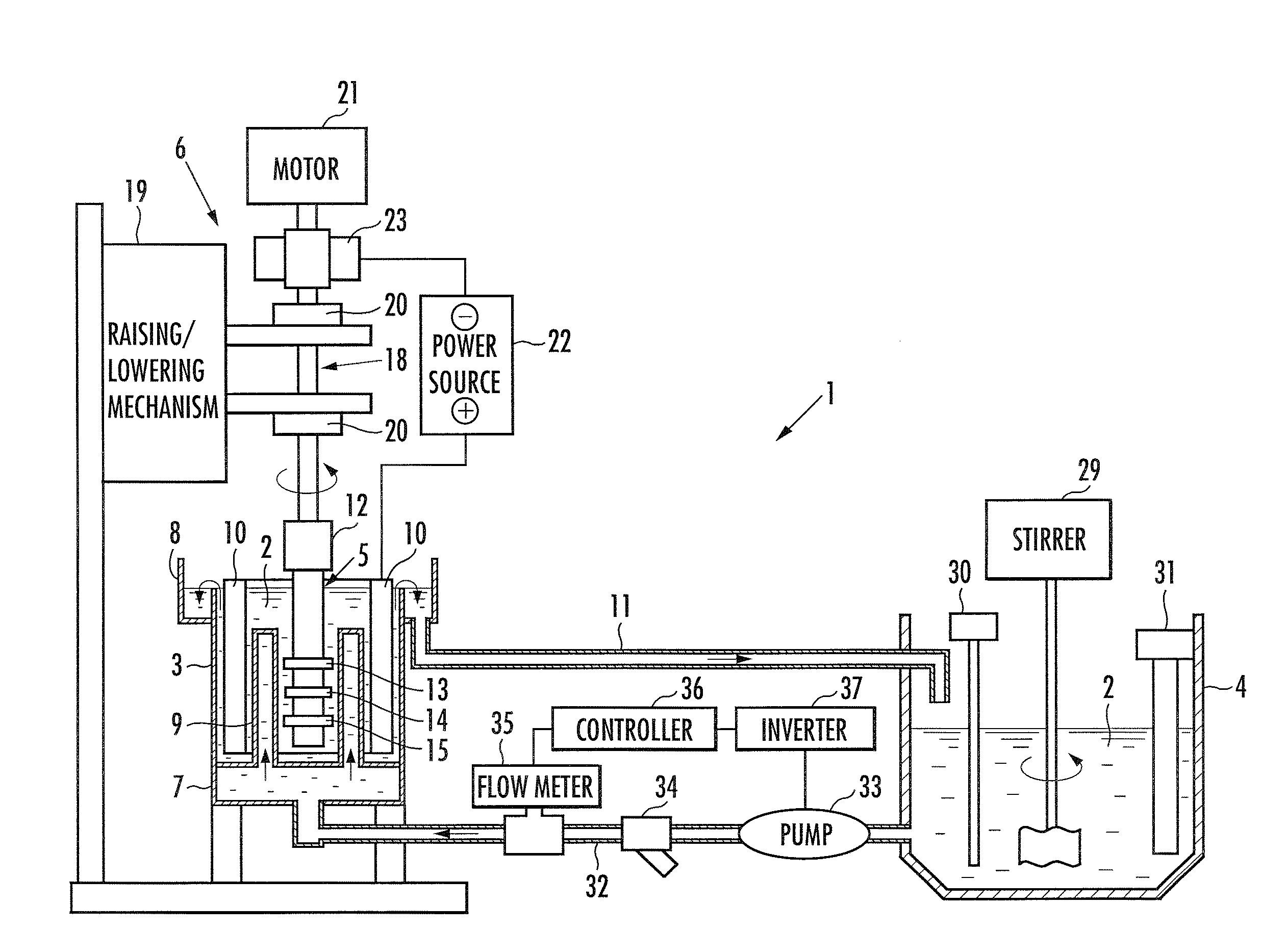
[0015]Thereby, the plating liquid is uniformly supplied to the whole surface of the to-be-plated portion, and a uniform flow of the plating liquid can be obtained over the whole surface of the to-be-plated portion. Further, since the shaft-shaped member is rotated, the plating liquid is supplied uniformly in the peripheral direction over the whole surface of the to-be-plated portion, and also the plating liquid is sufficiently stirred. Therefore, since the concentration of the respective metal ions in the plating liquid is kept constant over the whole surface of the to-be-plated portion, it is possible to form the magnetic alloy plating having a uniform composition and thickness on the surface of the shaft-shaped member in a short time. Also, it is possible to prevent the abnormal deposition from being caused.
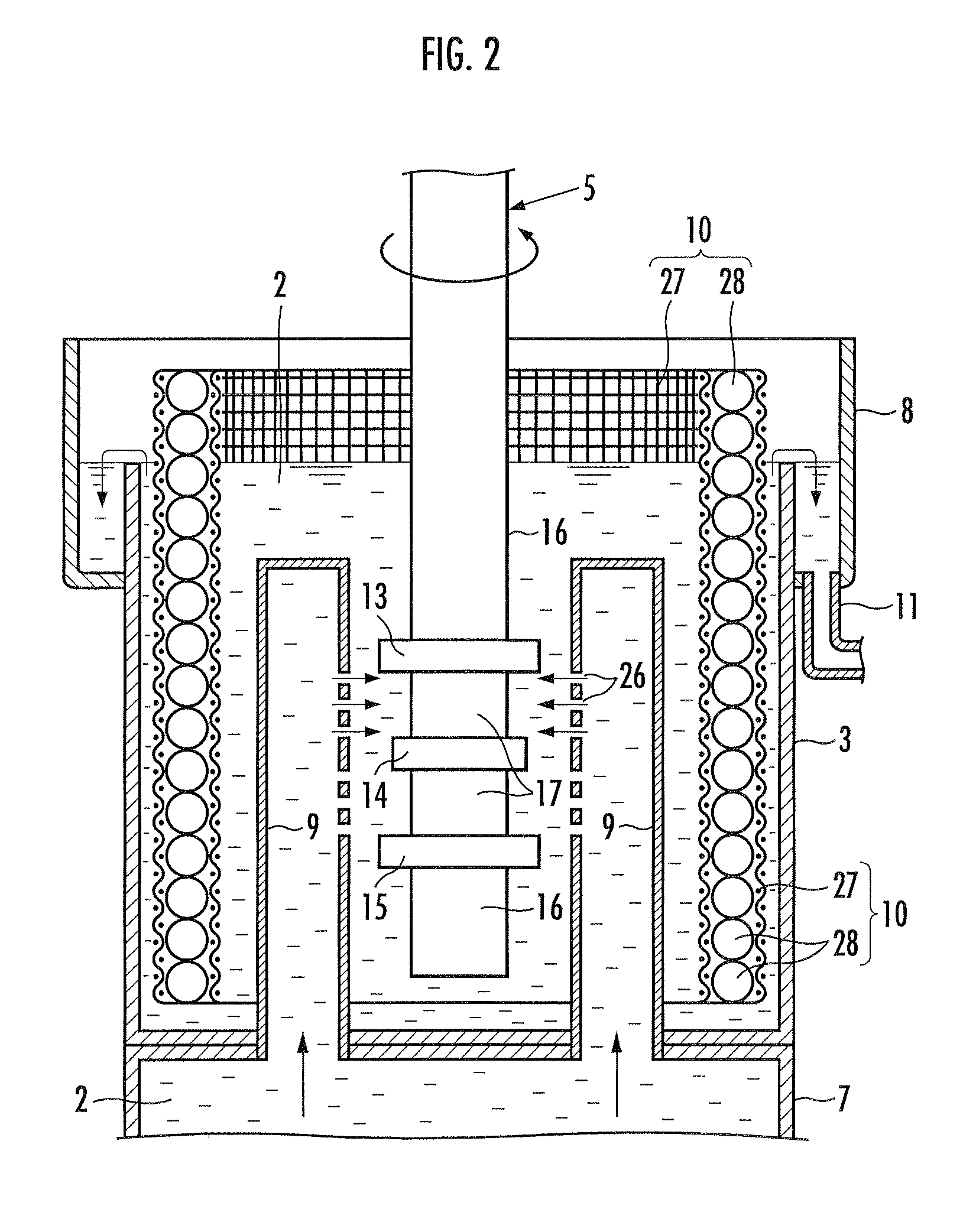
[0016]Further, in the plating apparatus according to the present invention, it is preferred that a plurality of the plating liquid discharge ports are respectively arranged on at least two virtual straight lines located on the outer peripheral surface of the plating liquid discharge nozzle in parallel with the axial direction of the shaft-shaped member, and that the respective plating liquid discharge ports are arranged so that when the shaft-shaped member is rotated, the plating liquid discharged from the plating liquid discharge port arranged on the one virtual straight line and the plating liquid discharged from the plating liquid discharge port arranged on the other virtual straight line are overlapped with each other on the shaft-shaped member in the axial direction thereof. With this configuration, when the shaft-shaped member is rotated, the plating liquid discharged from the plating liquid discharge port arranged on the one virtual straight line and the plating liquid discharged from the plating liquid discharge port arranged on the other virtual straight line are overlapped with each other on the shaft-shaped member in the axial direction, so as to be supplied to the surface of the to-be-plated portion of the shaft-shaped member. Thereby, the plating liquid is uniformly supplied to the whole surface of the to-be-plated portion in the axial direction, and the concentration of the respective metal ions in the plating liquid can be kept constant over the whole surface of the to-be-plated portion. Thus, it is possible to make uniform the composition and thickness of the formed magnetic alloy plating as a whole.
[0017]Further, the plating apparatus according to the present invention may also be configured such that the shaft-shaped member is vertically immersed in the plating liquid, that a plurality of the plating liquid discharge ports are arranged on at least two virtual straight lines located on the outer peripheral surface of the plating liquid discharge nozzle in parallel with the axial direction of the shaft-shaped member, and that the upper end of the first plating liquid discharge port located on the one virtual straight line is positioned higher than the lower end of the second plating liquid discharge port located on the other virtual straight line adjacent to the one virtual straight line, and also the lower end of the first plating liquid discharge port is positioned lower than the upper end of the third plating

Problems solved by technology

This results in a disadvantage that the plating rate cannot be increased.
This results in a disadvantage that there oc

Method used


Image

  • Plating apparatus
  • Plating apparatus
  • Plating apparatus

Examples


Embodiment Construction

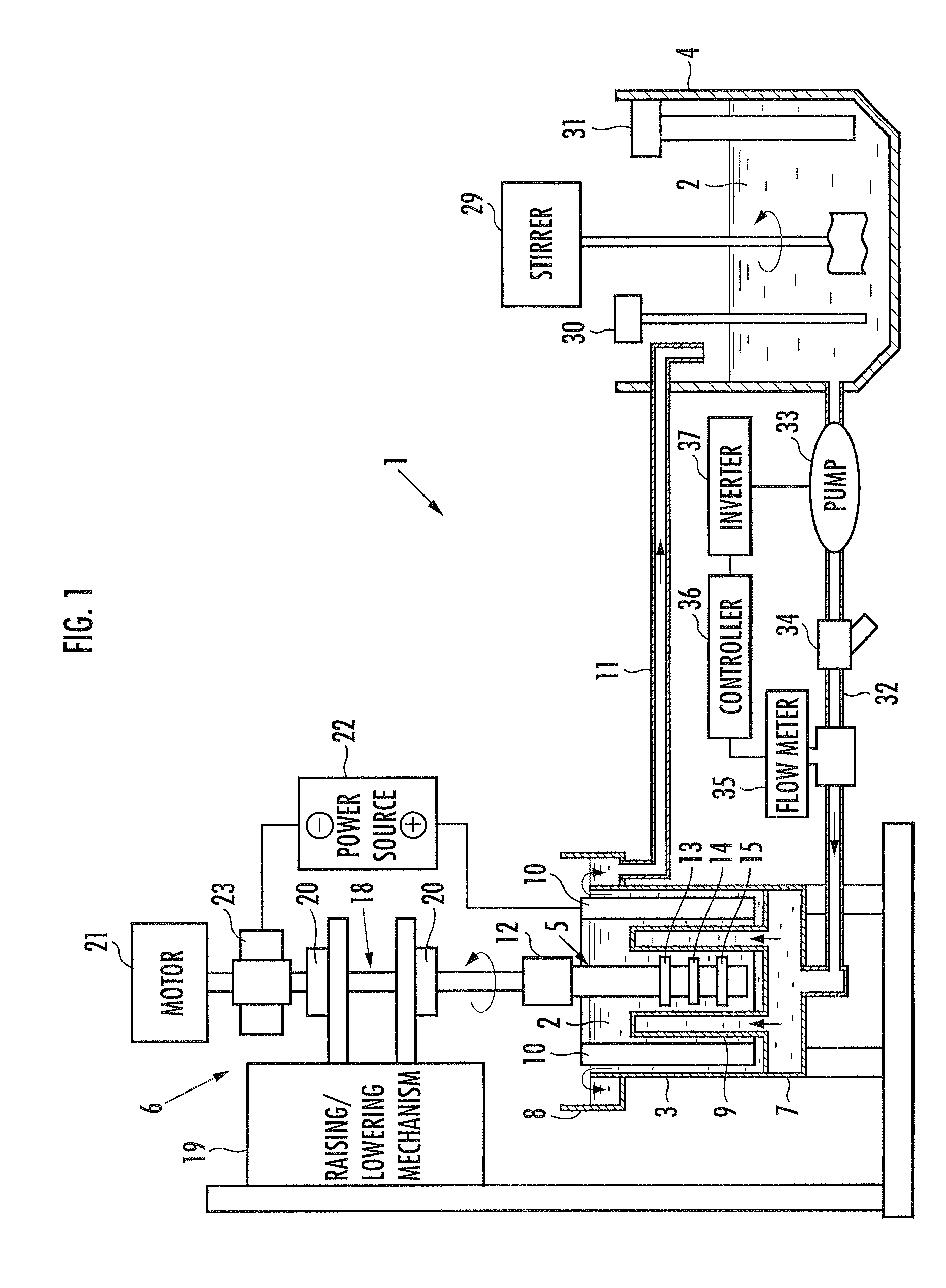
[0021]In the following, embodiments according to the present invention will be described in more detail with reference to the accompanying drawings. FIG. 1 is an explanatory front view showing a configuration example of a plating apparatus according to the present embodiment.

[0022]FIG. 2 is an explanatory sectional view showing an internal configuration of a plating tank of the plating apparatus according to the present embodiment shown in FIG. 1. FIG. 3 is an explanatory plan view showing an internal configuration of the plating tank of the plating apparatus according to the present embodiment shown in FIG. 1. FIG. 4 is an explanatory perspective view showing a plating liquid discharge nozzle of the plating apparatus according to the present embodiment shown in FIG. 1. Note that in FIG. 4, the portion surrounded by the circle A is shown on an enlarged scale.

[0023]The plating apparatus 1 includes a plating tank 3 which stores a plating liquid 2, a plating liquid adjusting tank 4 for...


PUM

PropertyMeasurementUnit
Diameteraaaaaaaaaa
Current densityaaaaaaaaaa
Magnetismaaaaaaaaaa

Abstract

A plating apparatus includes a plating tank for storing a plating liquid, and applies a magnetic alloy plating to a shaft-shaped member immersed in the plating liquid by using the shaft-shaped member as a cathode. The plating apparatus further includes a routable member configured to rotate the shaft-shaped member as a rotary shaft; annular shielding tools mounted on the outer peripheral surface of the shaft-shaped member; a plating liquid discharge nozzle including plating liquid discharge ports which are provided to face the shaft-shaped member so as to avoid the shielding tools; and an anode provided around the shaft-shaped member and the plating liquid discharge nozzle.

Description

TECHNICAL FIELD[0001]The present invention relates to a plating apparatus.BACKGROUND ART[0002]A magnetostriction type torque sensor is widely known as an instrument for detecting torque applied to a rotary shaft. The magnetostriction type torque sensor is configured to have two upper and lower annular magnetostrictive films formed on the outer peripheral surface of the rotary shaft, and is configured to detect torque of the rotary shaft by detecting a change in the magnetostrictive characteristic of the upper and lower magnetostrictive films which change is caused when the rotary shaft is torsionally deformed. In order to secure the detection accuracy of torque, it is necessary that the axial-direction thickness of the magnetostrictive film is uniform, and that the alloy composition of the magnetostrictive film is uniform.[0003]Conventionally, there is known a method shown in FIG. 5 as a method of applying plating to the surface of a shaft-shaped member used as a rotary shaft (Japan...

Claims


Application Information

Patent Timeline
IPC IPC(8): G01L3/10
CPCC25D17/02C25D21/10C25D17/008G01R33/18H01F41/24G01R33/063C25D7/00
Inventor YOSHIMOTO, NOBUHIKOKARASAWA, HITOSHIKOBAYASHI, KOJIDOI, MIZUHOHARATA, HITOSHI
Owner HONDA MOTOR CO LTD
Why Eureka
Try Eureka