
Diverless connector for bend restrictors and/or bend stiffeners

a technology of restrictors and connectors, applied in the direction of couplings, sealing/packing, borehole/well accessories, etc., can solve the problems of high cost of diving activity and support associated with diving activity, certain logistical, commercial and operational risks, and certain risks and dangers of coordinating installation activities with diving activities

Active Publication Date: 2011-06-28
DEEP SEA TECH
View PDF22 Cites 26 Cited by
  • Summary
  • Abstract
  • Description
  • Claims
  • Application Information

AI Technical Summary

Benefits of technology

"The patent describes a subsea connector that includes a guide funnel assembly and a latch assembly. The latch assembly has dogs that move radially in and out of the guide funnel assembly to secure the connector. The latch assembly can be manipulated using a remotely operated vehicle (ROV) and has a locking mechanism to prevent the dogs from moving outward when they are inserted into the shaft. The latch assembly can be unlocked to allow the shaft to be inserted and has a cam plate that controls the movement of the dogs. The technical effects of this invention include improved reliability and ease of installation for subsea connectors."

Problems solved by technology

Using the diver to connect the bend restrictor / limiter has certain risks and dangers associated with people operating heavy machinery in a subsea environment.
In addition, there are certain logistical, commercial, and operational risks associated with coordinating installation activity with diving activity.
Diving activity and support associated with the diving activity may also be expensive and increase the costs of installation of the bend restrictor / limiter.
Diver installation also may be slow and tedious, which may also increase costs and delay times for structure operation due to waiting for the diving operation to be completed.

Method used


Image

  • Diverless connector for bend restrictors and/or bend stiffeners
  • Diverless connector for bend restrictors and/or bend stiffeners
  • Diverless connector for bend restrictors and/or bend stiffeners

Examples


Embodiment Construction

[0028]In the context of this patent, the term “coupled” means either a direct connection or an indirect connection (e.g., one or more intervening connections) between one or more objects or components. The phrase “directly connected” means a direct connection between objects or components such that the objects or components are connected directly to each other so that the objects or components operate in a “point of use” manner.

[0029]In the context of this patent, the terms “latching dog” and “dog” refer to any mechanical device for holding, gripping, and / or fastening that comprises a spike, bar, hook, deadbolt, pin, or the like. The term “bend restrictor / limiter” refers to both a bend restrictor / limiter and a bend stiffener. Thus, a connector for a bend restrictor / limiter is also a connector for a bend stiffener and vice versa.

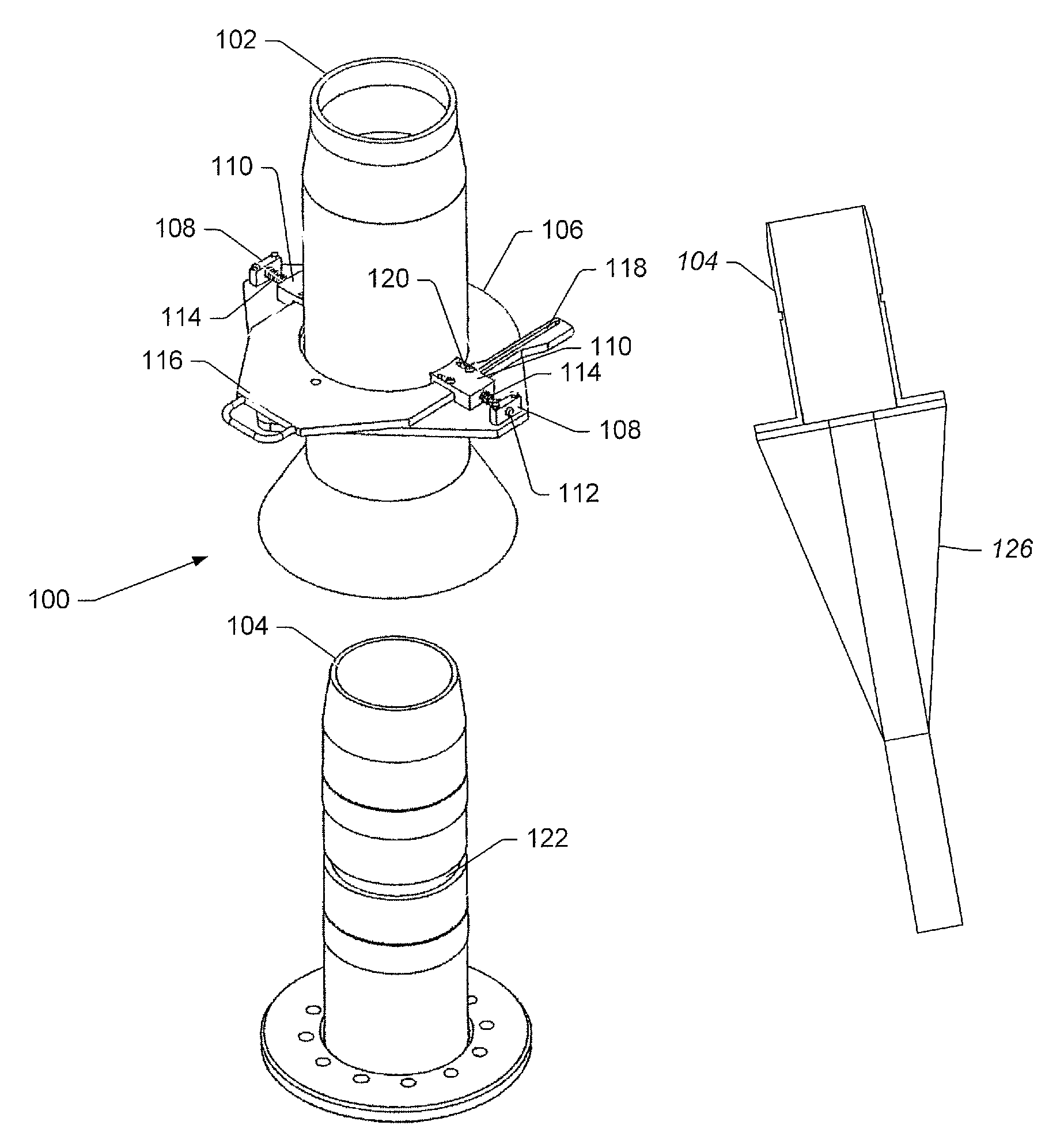
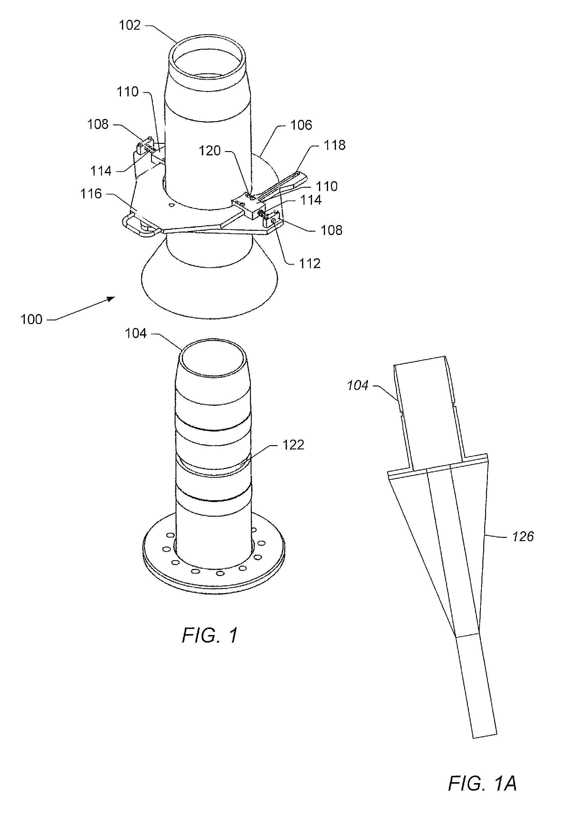
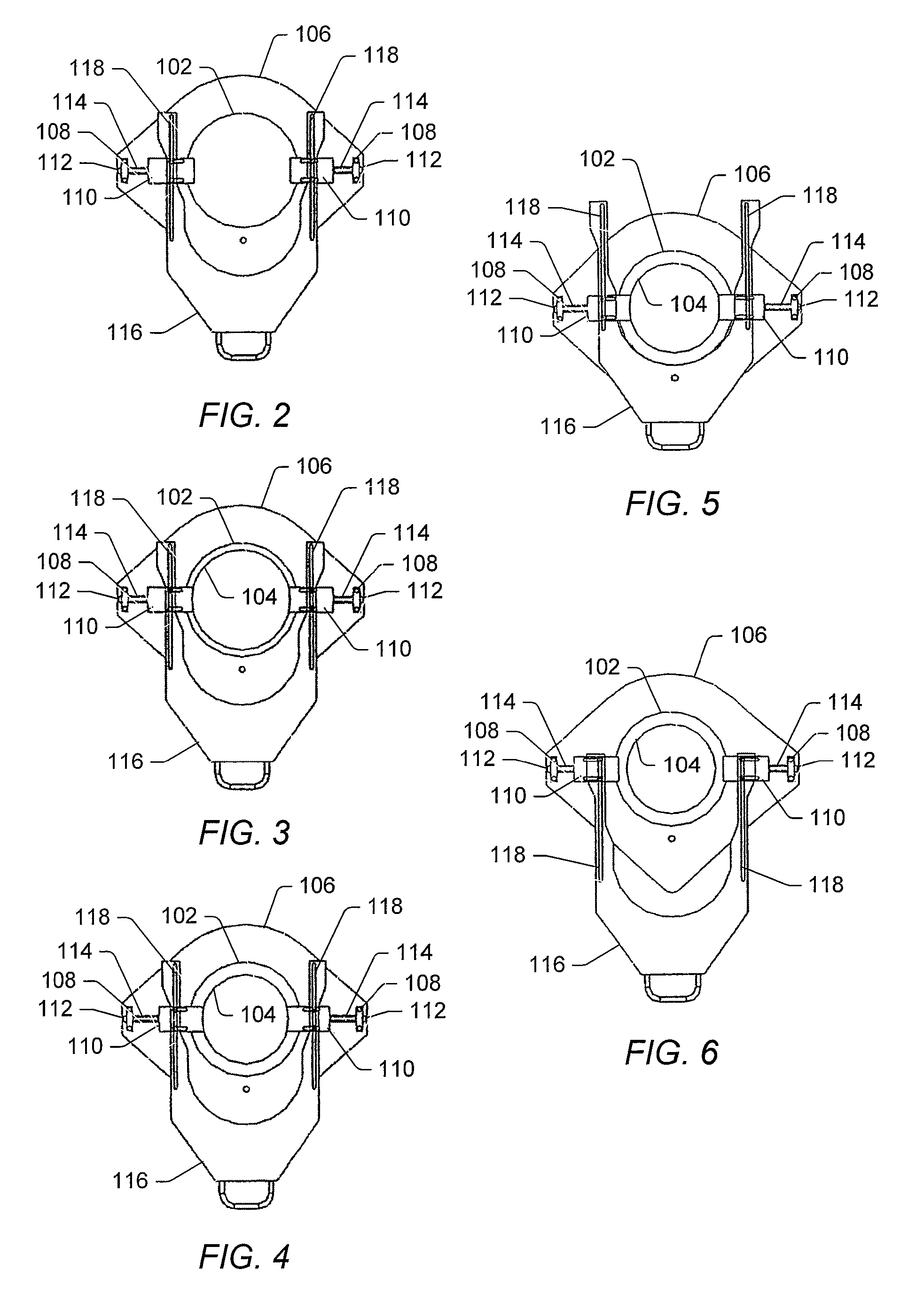
[0030]FIG. 1 depicts a representation of an embodiment of connector 100 that may be used for connecting bend restrictors / limiters and / or bend stiffeners to a...


PUM


Abstract

A subsea connector is disclosed. The connector includes a guide funnel assembly that may be coupled to a subsea structure. The guide funnel assembly may receive a shaft. The shaft may be coupled to a bend restrictor / limiter or a bend stiffener. The shaft may be received inside the guide funnel assembly. The shaft may include a recess. A latch assembly may be coupled to the guide funnel assembly. The latch assembly may include one or more dogs and a latch operating device. The dogs may be radially moveable in and out of the interior of the guide funnel assembly. The dogs may be inserted into the recess of the shaft to inhibit longitudinal axial movement between the shaft and the guide funnel assembly. The latch operating device may control the in and out radial movement of the dogs.

Description

PRIORITY CLAIM[0001]This patent application claims priority to U.S. Provisional Patent No. 60 / 807,090 entitled “DIVERLESS CONNECTOR FOR BEND RESTRICTORS / BEND LIMITERS” to Reddy filed on Jul. 12, 2006.BACKGROUND[0002]1. Field of the Invention[0003]The present invention relates to subsea connectors and devices for limiting the bend of flexible pipes or umbilicals used with subsea connections. More particularly, the invention relates to subsea bend restrictors / limiters and / or bend stiffeners that are installable using remotely operated vehicles (ROVs).[0004]2. Description of Related Art[0005]Bend restrictors (or bend limiters) and / or bend stiffeners are used to inhibit overbending of flexible pipes or cable, flowline, and / or umbilical risers where the risers attach to fixed or floating structures such as, but not limited to, subsea riser bases, wellhead connections, pipeline end manifolds (PLEMs), and fixed or floating offshore platforms. The flexible pipes, flowlines, and / or umbilical...

Claims


Application Information

Patent Timeline
Patent Type & Authority Patents(United States)
IPC IPC(8): E21B29/12
CPCE21B17/017E21B17/085F16L37/144F16L1/20F16L37/086F16L1/123Y10S285/92
Inventor REDDY, SANJAY KONDA
Owner DEEP SEA TECH
Learn More