Electronic completion installation valve

a technology of installation valve and electronic components, which is applied in the field of valves, can solve the problems of increased completion time, increased cost, and dangerous running of plugs, and achieves the effects of reducing the risk of plug failure, reducing the safety of plug failure, and increasing the time to achieve completion

Active Publication Date: 2011-06-28
HALLIBURTON MFG & SERVICES
View PDF10 Cites 19 Cited by
  • Summary
  • Abstract
  • Description
  • Claims
  • Application Information

AI Technical Summary

Benefits of technology

[0014]It is an object for the present invention to provide a method and apparatus for performing a completion run in a well bore which obviates or mitigates at least some of the disadvantages of the prior art.
[0017]It is a yet further object of at least one embodiment of the present invention to provide a method of completing a well bore which does not require control lines to surface or the use of wireline intervention.
[0019]By providing hydraulic control contained within the assembly, the valve can be remotely operated and does not require hydraulic control lines to the surface. Yet further, by including a downhole actuation mechanism, no physical connection with the surface is required.
[0035]Advantageously the method may include the step of pulling the string so that the monitored hydrostatic pressure reduces to be below the predetermined value and thereby reset the timer. This step allows an operator to prevent closure of the valve if desired.
[0040]In this way pressure can be applied by pumping fluid through the string against the closed valve. When the actuating mechanism senses a pressure spike it can open the valve.

Problems solved by technology

There are a number of disadvantages in using plugs run on wireline and the like.
Each run into the well increases the time to achieve completion and is therefore costly.
Running plugs can be dangerous during rig up / rig down.
Yet further, the costs can soar if the wire breaks in the hole and the plug has to be “fished” out.
Such arrangements don't allow wireline plugs to be run as they damage the coating.
Unfortunately in some environments it is more likely that wireline cannot be run as there is no wireline access to the desired location where the plug is to be positioned.
This effectively breaks a seal in the downhole arrangement and is therefore difficult both to engineer and to operate reliably remotely from the surface.
A second disadvantage is in arranging the control lines which must pass down the full length of the well.
In extended reach wells at great depths, this is costly and it is difficult to reliably control the pressure in the small diameter lines at the excessive depths.
Unfortunately these prior art disappearing plugs suffer from major limitations.
As they are closed during run-in, this means filling the tubing as the completion is run in the well becomes problematic and typically requires an addition piece of equipment i.e. the autofill sub or the circulation sub.
These tools are unreliable and prone to debris ingress.
Therefore in a well kick situation heavier completion fluid cannot easily be circulated into the well to regain control of the well.
The circulation sub does allow reverse flow but has a small flow by-pass area making it prone to blocking up with debris.
Debris is a common problem downhole, for example, as the tubing is threaded together pipe dope from each connection make up will find its way into the tubing I.D. In the prior art devices, this dope and any well debris will collect on top of the plugging device.
This can give problems with debris going into the mechanism and jamming it up and also with pressure transmittal through the debris itself.
A second disadvantage is that the majority of these devices operate by opening on a predetermined number of pressure cycles.
Often during surface operations pressures may be applied inadvertently to the tubing and it becomes confusing as to whether they constitute a cycle or not, therefore it becomes less clear how many cycles are left to open the plug / valve.
Additionally any shock loading during installation of the plug / valve can cause the internal mechanism to incrementally move, thus using up some cycles without knowledge by the operator.
In this way, there are a limited number of pressure related functions which can be carried out without the risk of the valve / plug opening.
However, if only one cycle is required to set the packer, there is excessive time wasted in creating nine further cycles to finally get the valve to open.

Method used


Image

  • Electronic completion installation valve
  • Electronic completion installation valve
  • Electronic completion installation valve

Examples


Embodiment Construction

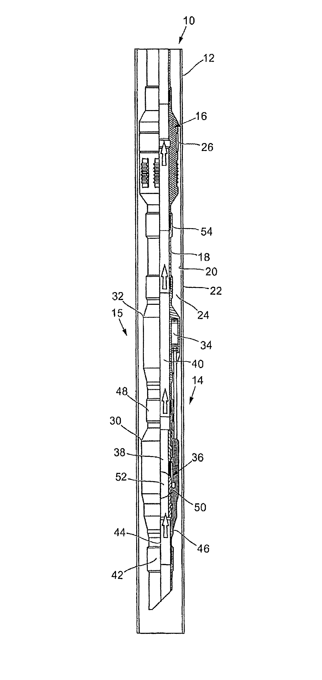
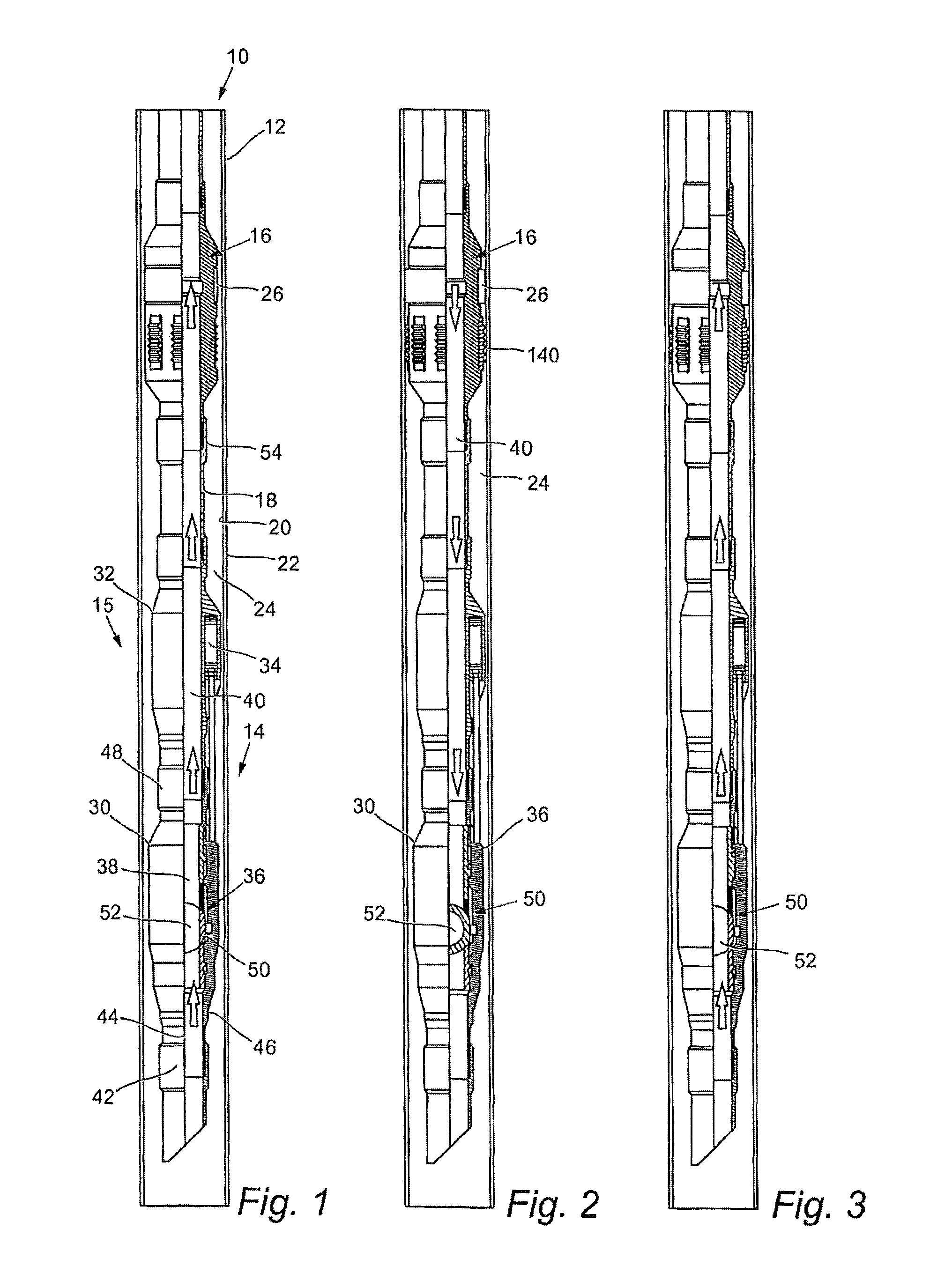
[0057]Reference is initially made to FIG. 1 of the drawings which illustrates a completion string, generally indicated by reference numeral 10, being run in a well bore 12 according to an embodiment of the present invention. It should be noted that wellbore 12 is cased i.e. it is lined, having been pre-drilled prior to insertion of the completion string 10.

[0058]Completion string 10 comprises a plurality of tubing sections which are cylindrical pipes fitted together via screw fittings at either end. At a lower end 14 of the string 10 there is located a production packer 16 and a completion assembly 15, according to an embodiment of the present invention.

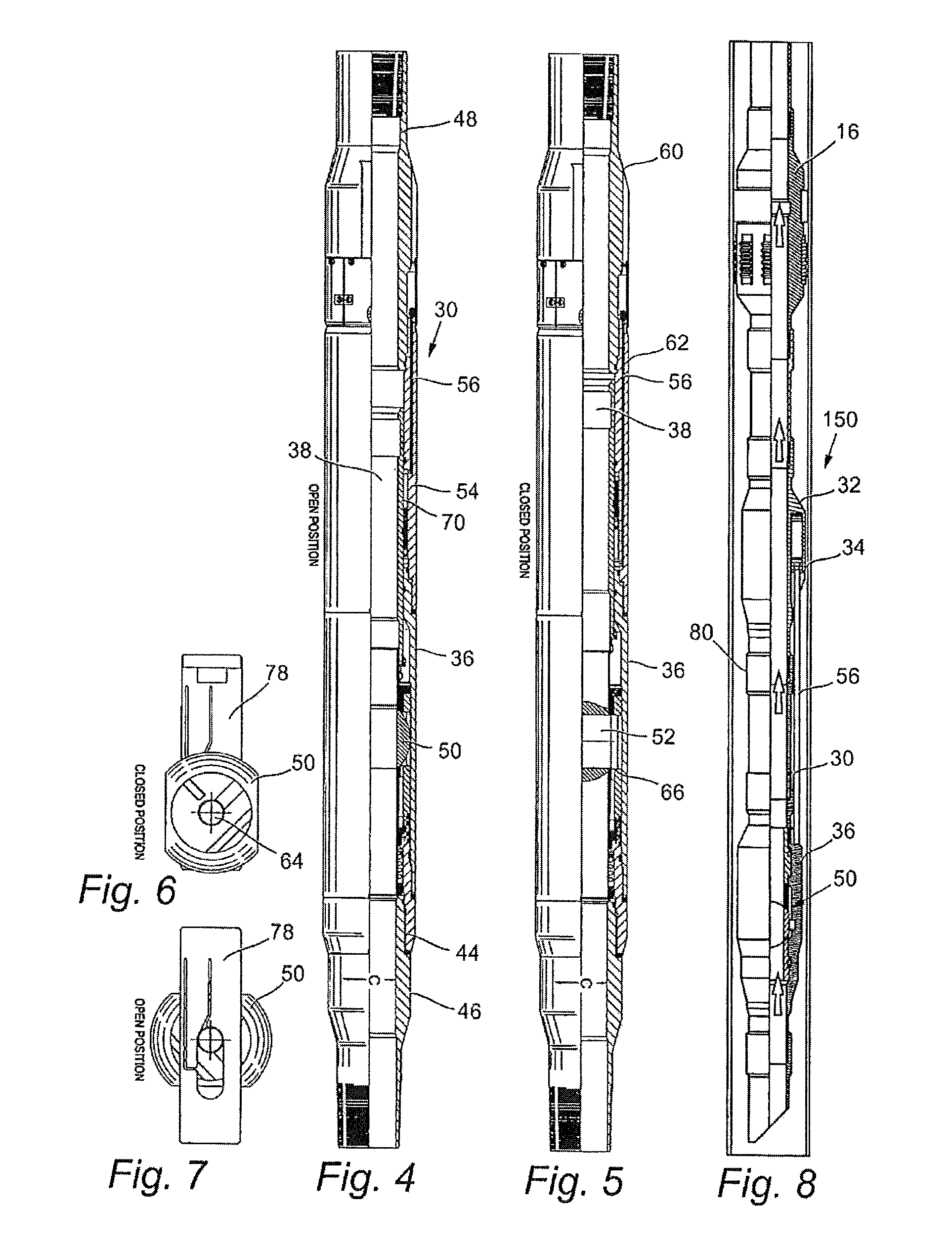
[0059]The completion assembly 15 comprises three sections. From above, the first section is an electronic actuating mechanism 32. This is connected to a hydraulic pump 34 which in turn is connected to a valve 30 containing a ball valve mechanism 36 towards the lower end 14 of the string 10. These parts will be described later in grea...


PUM


Abstract

Apparatus and method for a providing a completion assembly for running at an end of a completion string which provides a remotely operable tubing mounted valve used to control the flow of fluids through the tubing in hostile well conditions. The tubing mounted completion assembly has a tubular body for connection in the string below a production packer with a through bore from a first inlet and a first outlet coaxially aligned with the string; a downhole electronic actuating mechanism, a downhole hydraulic pump and a hydraulically operated ball valve member. The actuating mechanism operates the hydraulic pump to provide a hydraulic control line to control movement the valve member from a first position, where the member is open and a through bore is created between the inlet and outlet of the assembly, to a second position, where the valve seals the throughbore and, finally, back to the first position.

Description

BACKGROUND OF THE INVENTION[0001]1. Field of the Invention[0002]The present invention relates to valves used as plugs during completions of wells in oil and gas production. More particularly the present invention relates to an apparatus and method for providing a remotely operable tubing mounted valve used to control the flow of fluids through the tubing in hostile well conditions.[0003]2. Background of the Related Art[0004]When a well is completed, prior to production, a completion string is run into the well. On run in the string must be open to allow fluid to flow up the tubing of the string. In location the tubing must be sealed so that sufficient downhole pressure can be created to set the production packer mounted on the string and together provide a downhole barrier. The barrier thus allows pressure testing to be undertaken prior to the tubing string being opened so that produced oil can flow up the completion string to the surface.[0005]In order to achieve the opening and cl...

Claims


Application Information

Patent Timeline
Patent Type & Authority Patents(United States)
IPC IPC(8): E21B34/16E21B33/12
CPCE21B34/066E21B2034/002E21B2200/04
Inventor BROWN, IRVINE C.
Owner HALLIBURTON MFG & SERVICES
Why Eureka
Try Eureka