Spacecraft battery thermal management system

a battery and thermal management technology, applied in the field of spacecraft power systems, can solve the problems of reducing the area available to other payloads and bus equipment on the north and south facing sides, limiting the overall payload capabilities of spacecraft, etc., and achieve the effect of discharging excess heat from the battery

Active Publication Date: 2011-06-28
LOCKHEED MARTIN CORP
View PDF17 Cites 30 Cited by
  • Summary
  • Abstract
  • Description
  • Claims
  • Application Information

AI Technical Summary

Benefits of technology

[0006]The invention addresses the foregoing limitations of conventional spacecraft by providing a spacecraft battery thermal management system in which multiple radiator panels are thermally coupled to a battery using heat pipes. The heat pipes allow the radiator panels to be spatially displaced from the battery and positioned on opposite sides of the spacecraft. The transfer of heat between the radiator panels and the battery is controlled so that when one radiator panel is illuminated by the sun another radiator panel on an opposite side of the spacecraft dissipates excess heat from the battery. In this manner, the invention allows the radiator panels to be positioned on the East and West facing sides of a spacecraft in a geosynchronous orbit thereby freeing up area on the North and South facing sides for additional payload and bus equipment capacity.

Problems solved by technology

The thermal management systems used in conventional spacecraft, however, constrain the overall payload capabilities of the spacecraft.
When positioned on the North or South facing sides of the spacecraft, the spacecraft batteries and their conductively bonded thermal radiators significantly reduce the area available to other payload and bus equipment on the North and South facing sides of the spacecraft.

Method used


Image

  • Spacecraft battery thermal management system
  • Spacecraft battery thermal management system
  • Spacecraft battery thermal management system

Examples


Embodiment Construction

[0014]The detailed description of the invention set forth below in connection with the associated drawings is intended as a description of various embodiments of the invention and is not intended to represent the only embodiments in which the invention may be practiced. The detailed description includes specific details for the purpose of providing a thorough understanding of the invention. However, it will be apparent to those skilled in the art that the invention may be practiced without all of the specific details contained herein. In some instances, well known structures and components are shown in block diagram form in order to avoid obscuring the concepts of the invention.

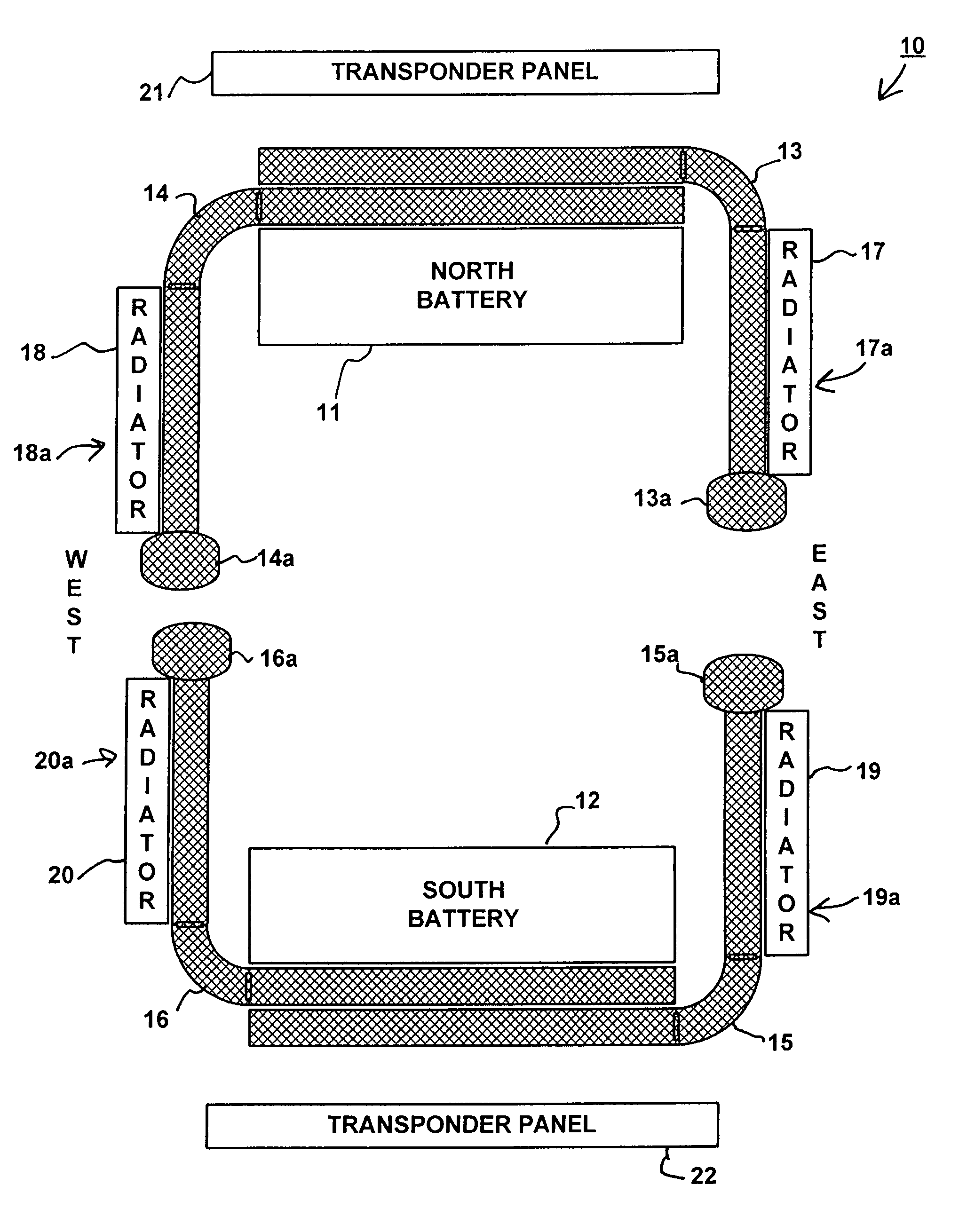
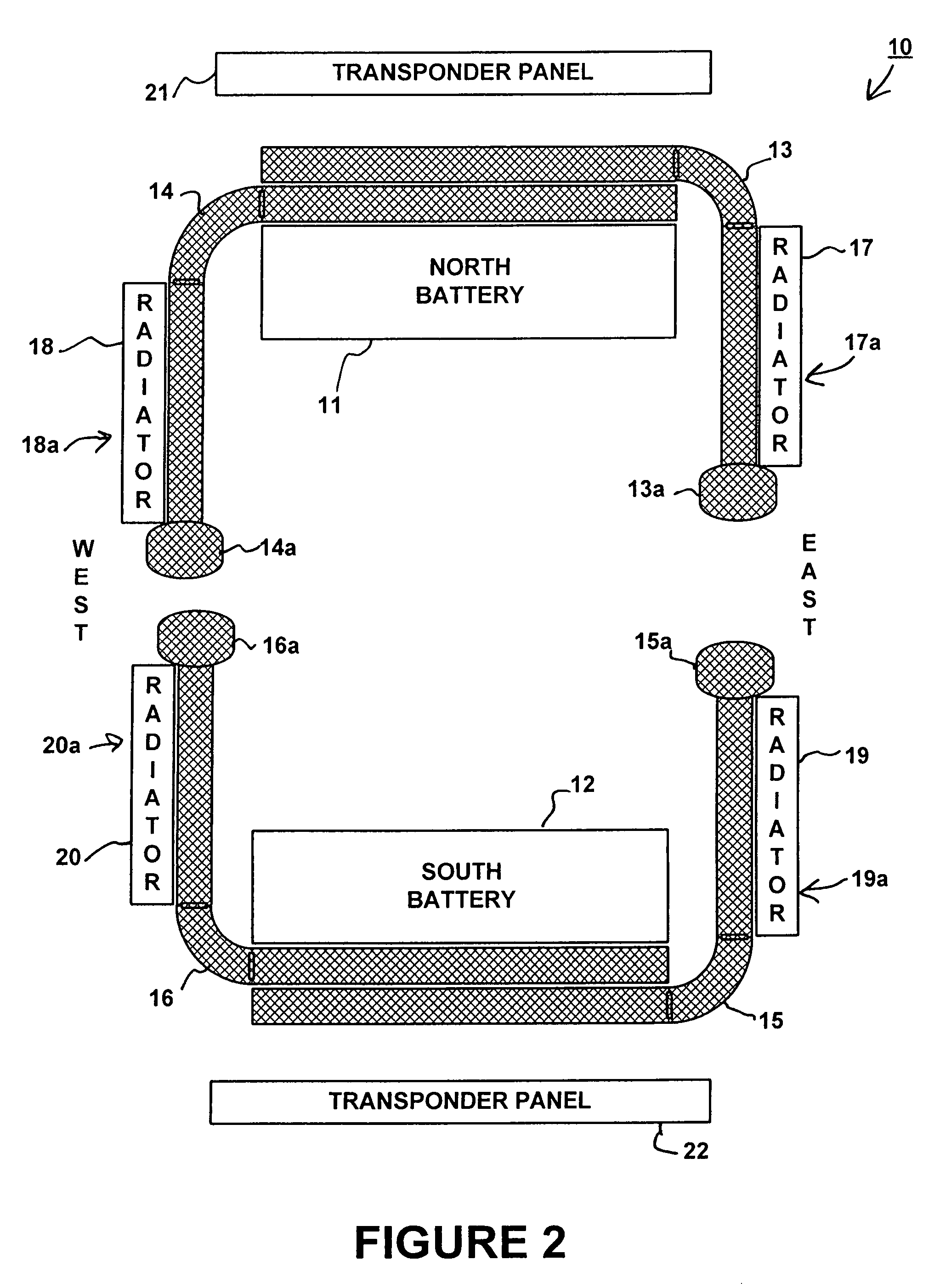
[0015]FIG. 2 is a block diagram depicting the arrangement of a spacecraft battery thermal management system according to one embodiment of the invention. Spacecraft battery thermal management system 10 depicted in FIG. 2 includes North battery 11, South battery 12, heat pipes 13-16, reservoirs 13a-16a and rad...


PUM


Abstract

A spacecraft battery thermal management system is provided that includes a battery, a first radiator panel and a second radiator panel. A first face of the first radiator panel is arranged to face a first direction and a first face of the second radiator panel is arranged to face a second direction opposite the first direction. A first heat pipe thermally couples the battery and the first radiator panel and is configured to control the transfer of heat between the battery and the first radiator panel. A second heat pipe thermally couples the battery and the second radiator panel and is configured to control the transfer of heat between the battery and the second radiator panel. Solar cells are optionally arranged on the faces of the first and / or second radiator panels.

Description

STATEMENT REGARDING FEDERALLY SPONSORED RESEARCH OR DEVELOPMENT[0001]Not applicable.BACKGROUND OF THE INVENTION[0002]The invention concerns spacecraft power systems and in particular is directed to a spacecraft battery thermal management system for controlling the temperature of batteries within a spacecraft.[0003]Spacecraft batteries must be maintained within specified temperature ranges during operation of the spacecraft. Excess heat generated by the batteries is dissipated using radiator panels thermally coupled to the batteries. The radiator panels are conductively bonded to one or more battery cells and are arranged with at least one face of the panel exposed to the cold temperatures of space. During charging operations, heat is supplied to the spacecraft batteries using power consuming heaters. The thermal management systems used in conventional spacecraft, however, constrain the overall payload capabilities of the spacecraft.[0004]Spacecraft operating in geosynchronous orbits...

Claims


Application Information

Patent Timeline
Patent Type & Authority Patents(United States)
IPC IPC(8): B64G1/58
CPCB64G1/425B64G1/506H01M10/5004H01M10/5006H01M10/502H01M10/5048H01M10/501H01M10/5083H01M10/5024H01M10/63H01M10/615H01M10/6571H01M10/6552H01M10/62H01M10/635H01M10/613Y02E60/10
Inventor WONG, HAMILTON
Owner LOCKHEED MARTIN CORP
Why Eureka
Try Eureka