
Cycle-based restoration in mesh networks utilizing bandwidth and flow considerations

a mesh network and cycle-based technology, applied in the field of mesh networks, to achieve the effect of enhancing restorability in the network

Inactive Publication Date: 2011-06-28
CIENA
View PDF12 Cites 11 Cited by
  • Summary
  • Abstract
  • Description
  • Claims
  • Application Information

AI Technical Summary

Benefits of technology

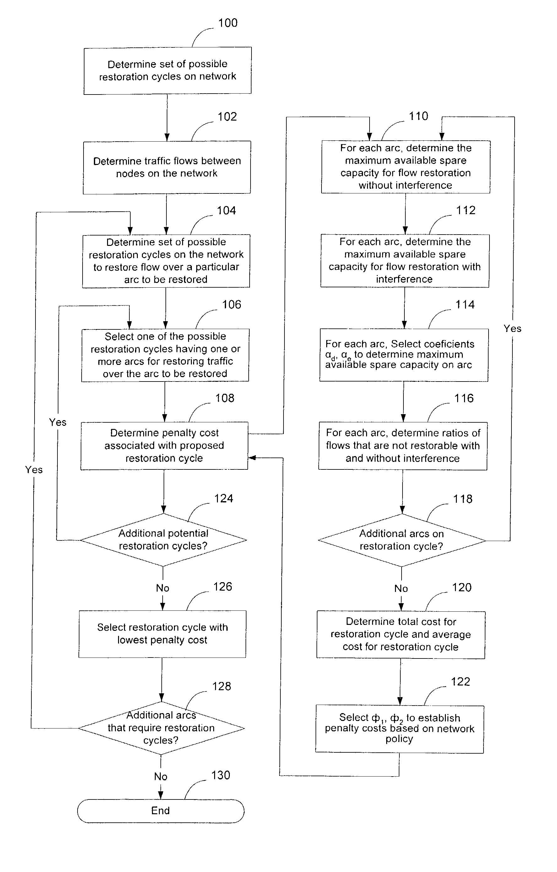
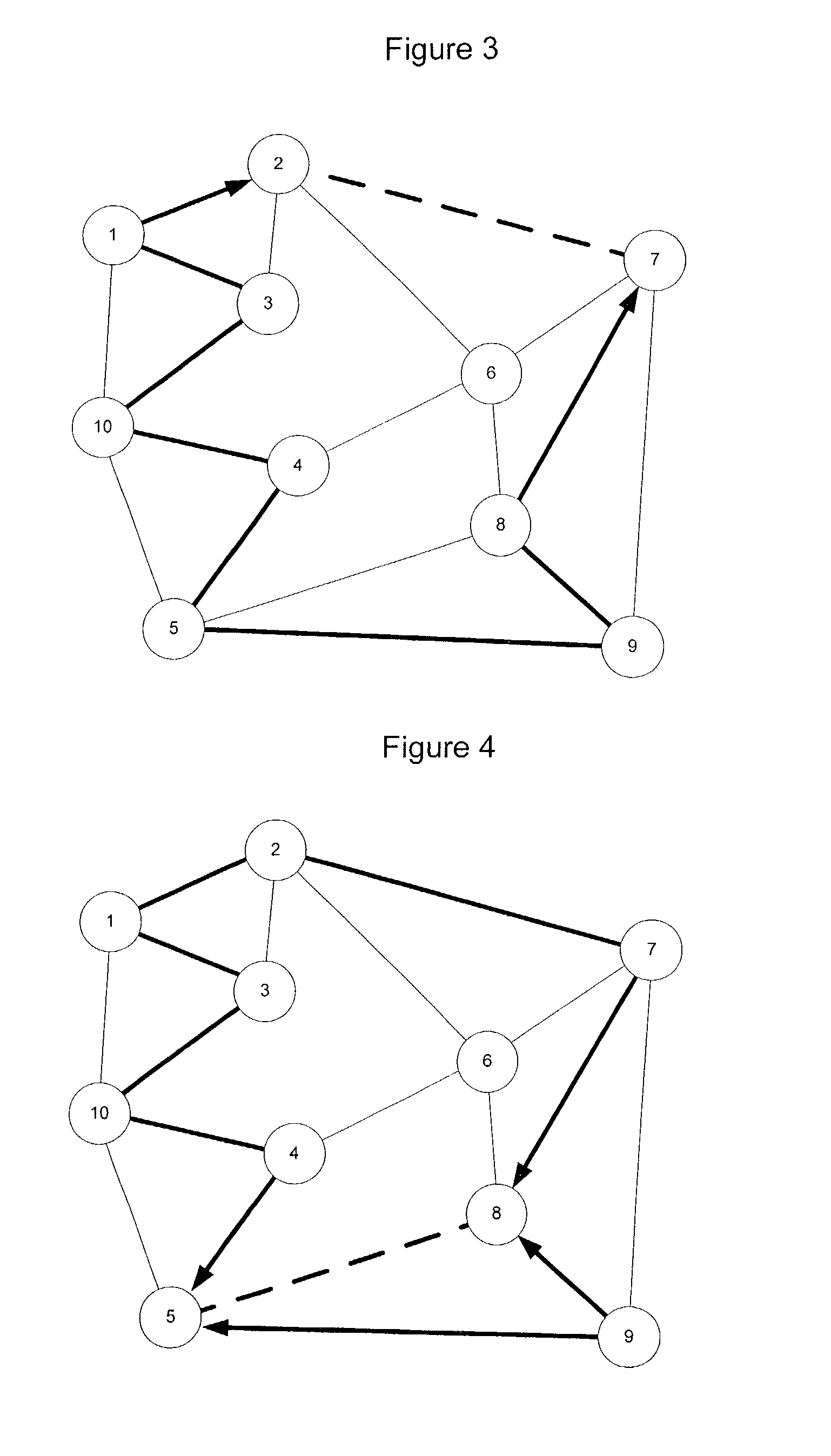
[0012]The present invention overcomes these and other drawbacks by providing a method of establishing restoration cycles on a mesh network that is able to account for individual flows and bandwidths on arcs in the mesh network. By considering flows and bandwidths over particular arcs or other sections of the network, it is possible to enhance restorability in the network and design redundancy into the network in a more effective manner.
[0013]According to an embodiment of the invention, a two step method for determining optimal P-cycles for a mesh network includes generating a set of possible restoration cycles, and selecting a subset of the cycles that optimize restorability links on the network, assuming a single link failure in the network. The subset of cycles may be selected by choosing one or more low-cost restoration cycles for each link to be restored. The cost of the restoration cycle may be based on the availability of capacity on the link to restore traffic with and / or without interference. The cost of the restoration cycle may also be based on network policy, such as whether the cost for the link should be based on the total cost for the entire restoration cycle or the average cost for the restoration cycle. Thus, embodiments of the invention provide flexibility in allowing for selection of which class, type, or priority of traffic to restore and which not to restore, whenever there is not enough capacity for complete restoration.

Problems solved by technology

The cost of the restoration cycle may be based on the availability of capacity on the link to restore traffic with and / or without interference.

Method used


Image

  • Cycle-based restoration in mesh networks utilizing bandwidth and flow considerations
  • Cycle-based restoration in mesh networks utilizing bandwidth and flow considerations
  • Cycle-based restoration in mesh networks utilizing bandwidth and flow considerations

Examples


Embodiment Construction

[0018]The following detailed description sets forth numerous specific details to provide a thorough understanding of the invention. However, those skilled in the art will appreciate that the invention may be practiced without these specific details. In other instances, well-known methods, procedures, components, protocols, algorithms, and circuits have not been described in detail so as not to obscure the invention.

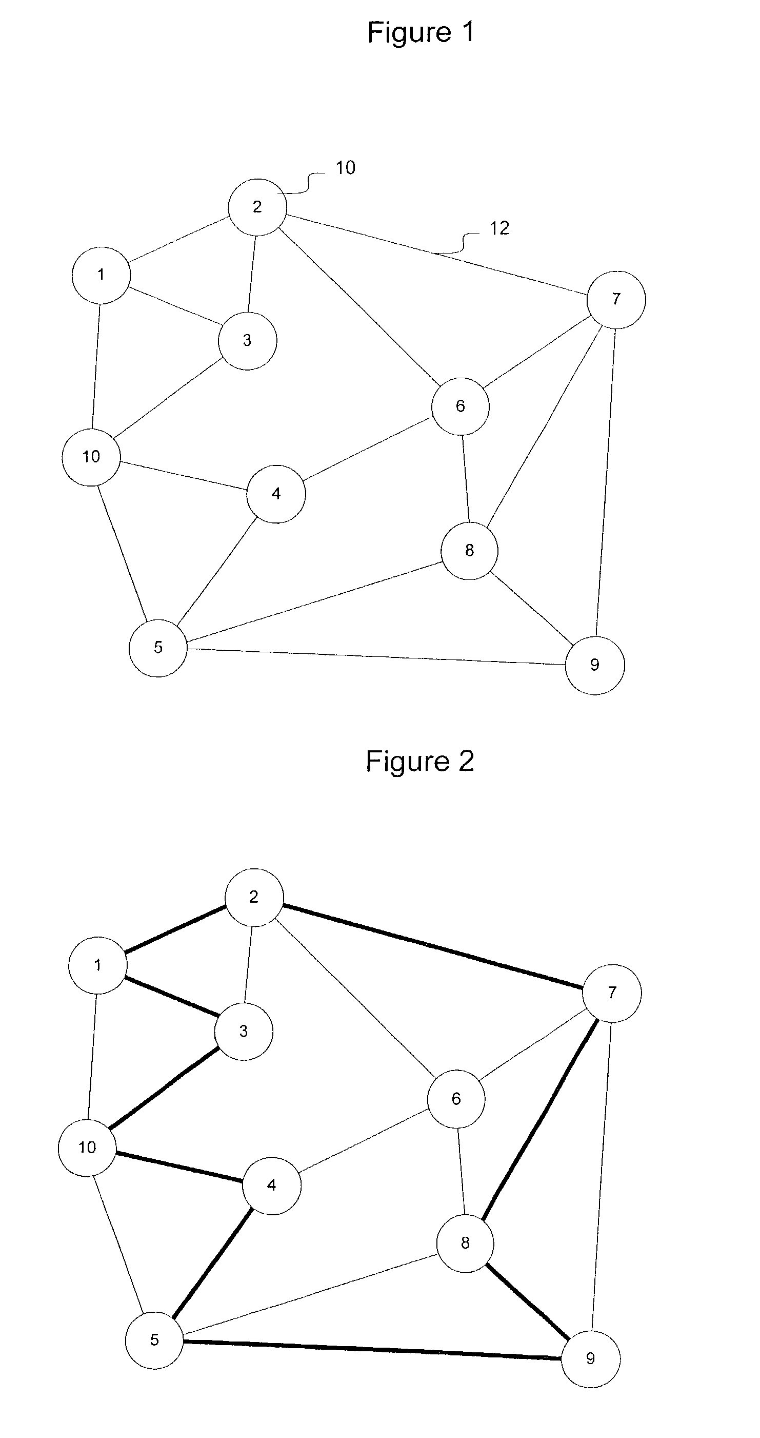
[0019]FIG. 1 illustrates an example mesh network G including a set of nodes N (element 10 in FIG. 1) and a set of arcs A (elements 12 in FIG. 1). Nodes N are interconnected by arcs A, although not every node is connected to every other node by a direct arc. The network G will be defined as G={N, A}, where N is the set of nodes and A is the set of arcs of this network. The arcs are undirected.

[0020]A(i), (iεN) will be defined as the set of arcs connected to node i. In the following discussion, it will be assumed that |A(i)|≧2; if this condition is not met there is only one...


PUM


Abstract

A two step method for determining restoration cycles for a mesh network includes generating a set of possible restoration cycles, and selecting a subset of low-cost restoration cycles on the network. The cost of a restoration cycle may be based, in part, on the availability of capacity on the link to restore traffic with and / or without interference, and network policy. Enabling the restoration cycles to be determined based on the bandwidth capacity of the restoring link, the flows carried by the other link, and other network policy considerations enables embodiments of the invention to account for traffic class, priority, and other traffic considerations when selecting restoration cycles on the network. Identifying arcs on the network with relatively high cost restoration cycles allows portions of the network to be targeted for increased capacity.

Description

CROSS REFERENCE TO RELATED APPLICATIONS[0001]This application claims the benefit of and claims priority to U.S. Provisional Patent Application. No. 60 / 451,898, filed Mar. 4, 2003, entitled “Cycle-Based Restoration Algorithm With Bandwidth and Flow Considerations for Mesh Networks: Developing the Objective Function”.BACKGROUND OF THE INVENTION[0002]1. Field of the Invention[0003]The present invention relates to mesh networks and, more particularly, to a method and apparatus for cycle-based restoration in mesh networks.[0004]2. Description of the Related Art[0005]Data communication networks may include various computers, servers, nodes, routers, switches, hubs, proxies, and other devices coupled to and configured to pass data to one another. These devices will be referred to herein as “network devices.” Data is communicated through the data communication network by passing data packets (or cells, frames, or segments) between the network devices by utilizing one or more communication l...

Claims


Application Information

Patent Timeline
Patent Type & Authority Patents(United States)
IPC IPC(8): H04L1/00H04L12/26H04L12/28
CPCH04L45/125H04L45/28H04L45/22
Inventor WANG, GUO-QIANGALFA, ATTAHIRU SULE
Owner CIENA
Learn More