Gas bags for massaging device

a massaging device and gas bag technology, applied in the field of gas bags for massaging devices, can solve the problem that the gas bag may not be returned to the contracted condition, and achieve the effect of increasing the elastic range, increasing the elongating and contracting distance, and increasing the elastic rang

Inactive Publication Date: 2008-04-03
TOYOTA BOSHOKU KK
View PDF6 Cites 15 Cited by
  • Summary
  • Abstract
  • Description
  • Claims
  • Application Information

AI Technical Summary

Benefits of technology

[0009]According to this embodiment, the gas bag is annealed while the bellows-shaped portion is compressed. Therefore, when the gas bag is in a contracted condition, the bellows-shaped portion of the gas bag may preferably have a length shorter than the length of a bellows-shaped portion of an unannealed gas bag. As a result, the gas bag may have an increased elongating and contracting distance (stroke). In addition, because the gas bag is annealed, the bellows-shaped portion of the gas bag may have an increased elastic range. The increased elastic range may contribute to increase of the stroke of the gas bag.
[0010]The gas bag may be formed from a thermoplastic crystalline resin. The gas bag formed from the thermoplastic crystalline resin may have increased restorability. Therefore, the gas bag can be reliably restored to an original length when it is contracted.
[0011]Also, the gas bag may be formed from a thermoplastic crystalline elastomer. The gas bag formed from the thermoplastic crystalline elastomer may have increased durability or flexibility. Therefore, the gas bag (the bellows-shaped portion) is not be easily broken even if the gas bag is repeatedly elongated and contracted. This may lead to a prolonged working life.
[0012]Further, the gas bag may be formed from a thermoplastic polyester elastomer. The thermoplastic polyester elastomer has good heat stability. Therefore, the gas bag formed from the thermoplastic polyester elastomer may preferably be used at high temperatures.

Problems solved by technology

However, if the bellows-shaped portion of the gas bag is elongated beyond an elastic region thereof in order to increase the stroke of the bas bag, the gas bag may possibly be no longer returned to the contracted condition due to plastic deformation that can be produced in the bellows-shaped portion thereof.

Method used


Image

  • Gas bags for massaging device
  • Gas bags for massaging device
  • Gas bags for massaging device

Examples


example

[0028]In order to evaluate some properties of the present gas bag, a plurality of different gas bags (Gas Bags A, A′, B, B′, Z and Z′) were prepared.

Gas Bags A and A′:

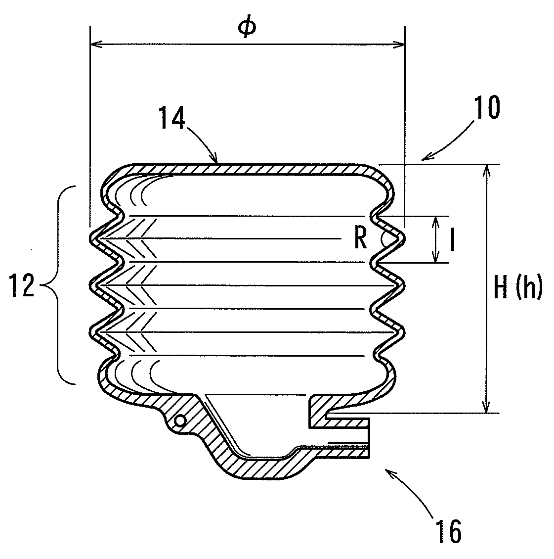
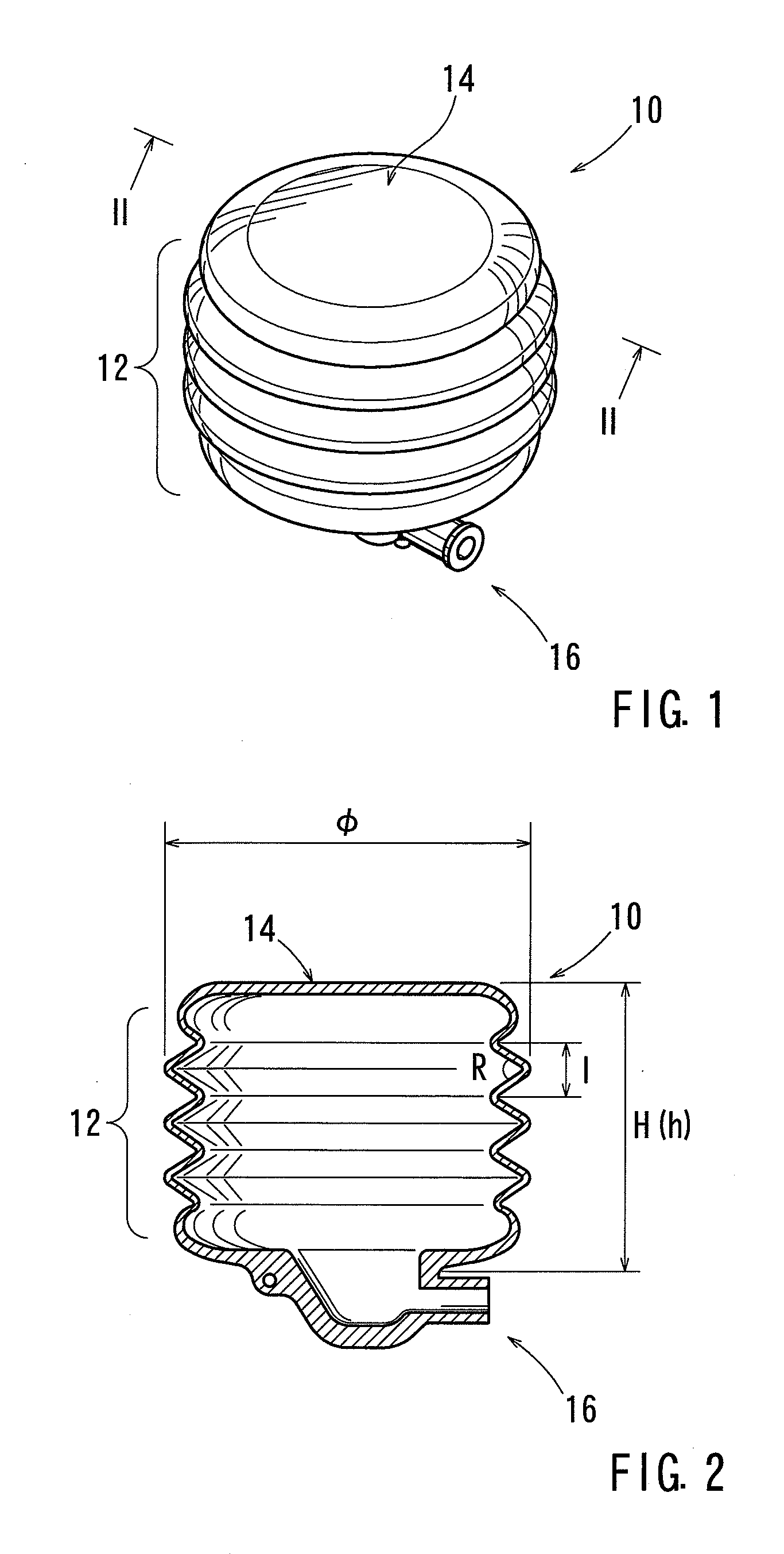
[0029]A thermoplastic polyester elastomer (TPEE) (“PELPRENE” (registered trademark) manufactured by TOYOBO CO., LTD.) was molded by blow molding, thereby forming an intermediate gas bag (an untreated gas bag), which will be referred to as Gas Bag A′. Gas Bag A′ thus formed had a length (a natural length) h of 44.3 mm. Thereafter, Gas Bag A′ thus formed was annealed at 165±8° C. while the bellows-shaped portion thereof is compressed so as to have a length of 22 mm shorter than the natural length h (44.3 mm) thereof. Thereafter, heated Gas Bag A′ was slowly cooled, thereby producing a final gas bag (a treated gas bag), which will be referred to as Gas Bag A. Gas Bag A thus produced had a length (a compressed natural length) H of 22 mm. Dimensions of Gas Bags A′ and A are shown in Table 1. Further, references φ, I, R and ...


PUM


Abstract

A gas bag for a massaging device is taught that preferably includes a bellows-shaped portion that is capable elongating and contracting by air supply and air discharge. The gas bag is formed from a thermoplastic resin. The gas bag is annealed while the bellows-shaped portion is compressed so as to have a length shorter than a natural length at the time of molding thereof.

Description

[0001]This application claims priority to Japanese patent application serial number 2006-266964, the contents of which are incorporated herein by reference.BACKGROUND OF THE INVENTION[0002]The present invention relates to gas bags for a massaging device (which will be hereinafter simply referred to as “gas bags”). More particularly, the present invention relates to gas bags that can be used in massaging chairs, massaging beds, vehicle seats having a massaging function or other such devices.[0003]A pneumatic massage chair is already known. Conventionally, such a massaging chair having a plurality of gas bags (massaging elements) that are embedded therein. Each of the gas bags may preferably be inflated and deflated (elongated and contracted) by air supply and air discharge, so as to push or massage a user sitting in the chair. Generally, the massaging chair may preferably be covered by a covering member. Therefore, the gas bag, when inflated or elongated, may preferably project from ...

Claims


Application Information

Patent Timeline
Patent Type & Authority Applications(United States)
IPC IPC(8): B65D30/00
CPCA61H9/0078A61H2201/0138B60N2/448A61H2205/081B60N2/4415A61H2201/0149B60N2/976B60N2/914
Inventor KITOU, MASAYUKI
Owner TOYOTA BOSHOKU KK
Why Eureka
Try Eureka