Hollow fiber membrane for treating liquids
a hollow fiber membrane and liquid treatment technology, applied in the direction of membranes, filtration separation, separation processes, etc., can solve the problems of high disposal cost of the large amount of diatomaceous earth required, inability to incinerate used diatomaceous earth, and insufficient etc., to suppress the formation of cake layers, excellent filtration stability, and adequate flexibility of the inner surface
- Summary
- Abstract
- Description
- Claims
- Application Information
AI Technical Summary
Benefits of technology
Problems solved by technology
Method used
Image
Examples
example 1
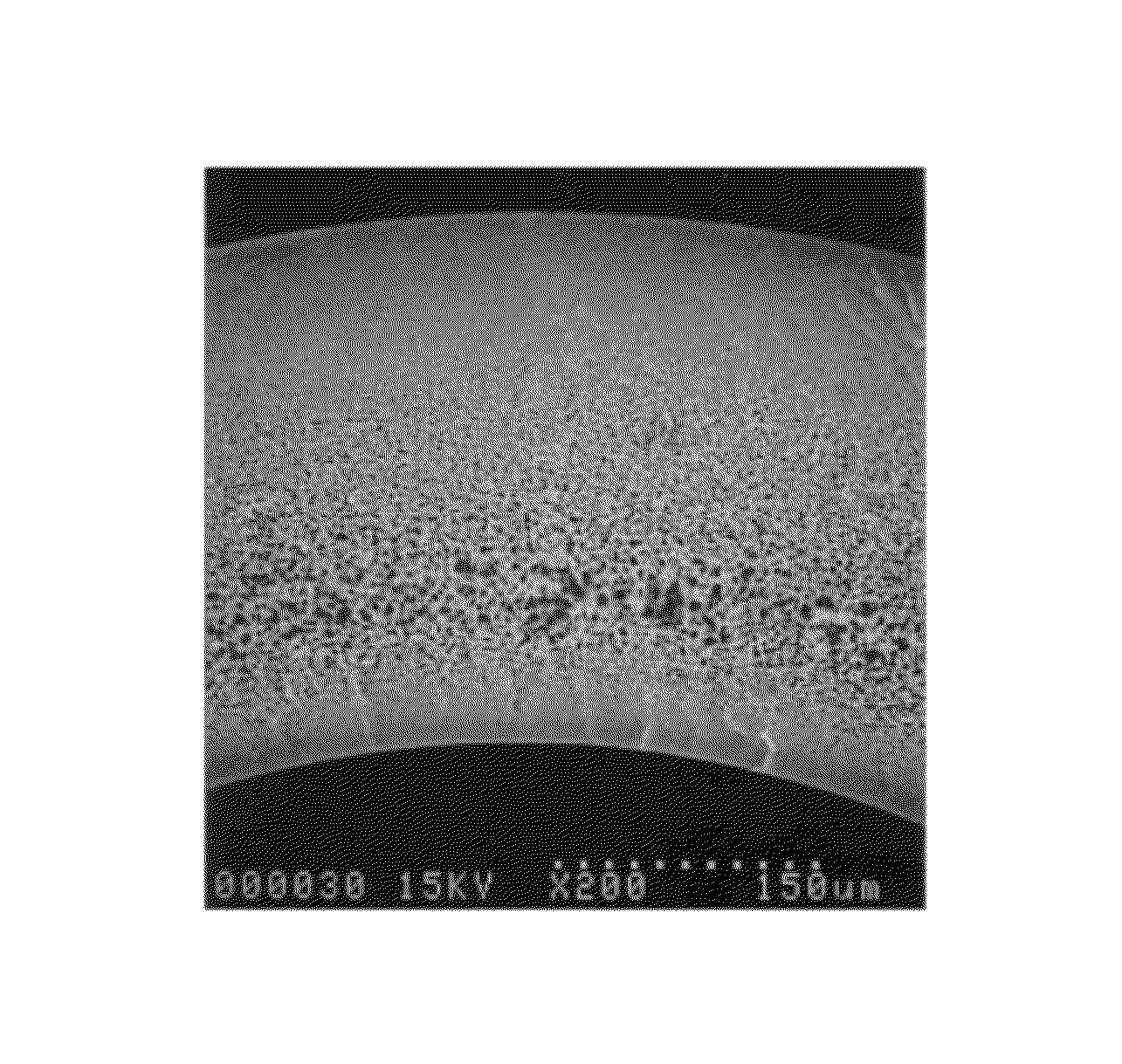
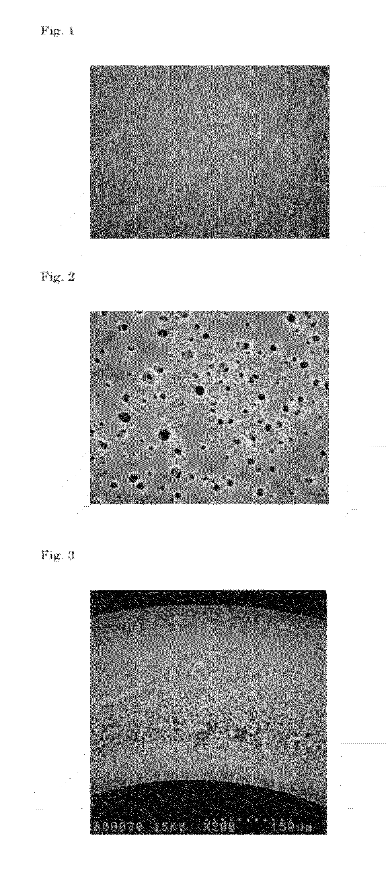
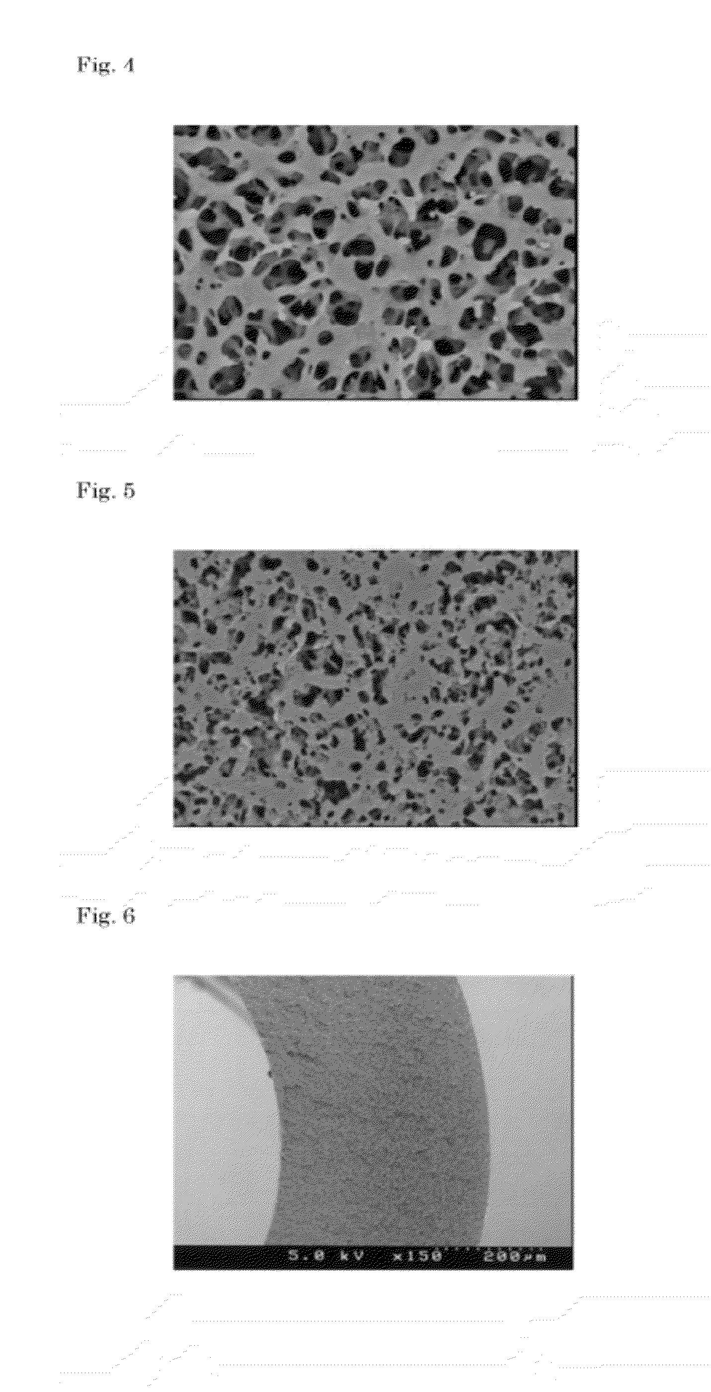
[0119]PES (Sumika EXCEL® 4800P manufactured by Sumitomo Chemtex) (19.0 wt. %), PVP (Kolidone® K30 manufactured by BASF) (3.0 wt. %), NMP manufactured by Mitsubishi Chemical Corporation (35.1 wt. %) and TEG manufactured by MITSUI CHEMICALS, INC. (42.9 wt. %) were mixed and dissolved at 80° C. for four hours to form a homogenous solution. The obtained solution was decompressed at from an atmospheric pressure to −700 mmHg. Immediately afterward, the system was sealed so as not to change the composition of the solution due to the volatilization of the solvent or the like, and the solution was left to stand for two hours so as to be defoamed. The resulting solution was used as a membrane-forming solution. A mixture of NMP (34.875 wt. %), TEG (42.675 wt. %) and RO water (22.5 wt. %) was prepared as an inner liquid. The membrane-forming solution and the inner liquid were discharged from the annular portion and the center portion of a double tube nozzle, respectively; afterward, the resulta...
example 2
[0123]A hollow fiber membrane was produced using the same method as in Example 1, except that the membrane-forming solution was formed with PES (20.0 wt. %), PVP (K30) (5.0 wt. %), NMP (33.75 wt. %) and TEG (41.25 wt. %); the inner liquid was formed with a mixture of NMP (36.0 wt. %), TEG (44.0 wt. %) and RO water (20.0 wt. %) and a different condition was used to feed the hollow fiber membrane to the coagulating bath. The obtained hollow fiber membrane was wound up. In the coagulating bath, three cylindrical guides with diameters of 100 mm were arranged to gradually change the feeding direction of the hollow fiber membrane to pull it out from the coagulating bath. More specifically, the feeding direction of the hollow fiber membrane was changed at the curvature radius of 50 mm, and at three turning points. The immersion depth for the hollow fiber membrane in the coagulating bath was a maximum of 800 mm, and the feeding distance for the hollow fiber membrane in the same bath was 2,0...
example 3
[0125]A hollow fiber membrane was produced using the same method as in Example 1, except that the temperature of the external coagulating liquid was set to 40° C. The inner diameter and the thickness of the obtained hollow fiber membrane were 1,180 μm and 340 μm, respectively. Table 1 shows the results.
[0126]Flux was measured using the same method as in Example 1. Flux sustainability and recoverability by washing were both high, i.e., 81% and 90%, respectively. The structure of the hollow fiber membrane was the same as that in Example 1. The size change of the inner surface of the hollow fiber membrane in the direction along the cross section was measured according to ((|B|−|A|) / membrane thickness×100(%)), with the result of 7.0%.
PUM
| Property | Measurement | Unit |
|---|---|---|
| pressure | aaaaa | aaaaa |
| thickness | aaaaa | aaaaa |
| internal diameter | aaaaa | aaaaa |
Abstract
Description
Claims
Application Information
 - R&D
- Intellectual Property
- Life Sciences
- Materials
- Tech Scout
- Unparalleled Data Quality
- Higher Quality Content
- 60% Fewer Hallucinations
Browse by: Latest US Patents, China's latest patents, Technical Efficacy Thesaurus, Application Domain, Technology Topic, Popular Technical Reports.
© 2025 PatSnap. All rights reserved.Legal|Privacy policy|Modern Slavery Act Transparency Statement|Sitemap|About US| Contact US: help@patsnap.com


