Electrical connection device

a technology of electrical connection and connection structure, which is applied in the direction of coupling device connection, winding, association with control/drive circuit, etc., can solve the problems of complicated bolt fastening operation, inability to reliably ensure safety of connection structure, and inability to fasten bolts. to ensure the safety, the effect of reducing maintenance and inspection costs and facilitating replacement of parts

Inactive Publication Date: 2011-07-05
AISIN AW CO LTD
View PDF14 Cites 2 Cited by
  • Summary
  • Abstract
  • Description
  • Claims
  • Application Information

AI Technical Summary

Benefits of technology

[0006]Thus, it is desired to implement an electrical connection device capable of electrically connecting and disconnecting a rotating electrical machine and an inverter device to and from each other in a case in a simple and safe manner.
[0031]With this structure, the rotating electrical machine fixed to the first case, and the inverter device fixed to the second case can be separated from each other in a state in which the opposing portions of the first bus bar and the second bus bar are released from the connection member. This facilitates, e.g., maintenance such as inspection or service because maintenance work can be performed on an individual component (the rotating electrical machine or the inverter device), rather than being performed on the combination of the rotating electrical machine and the inverter device. This also facilitates replacement of parts due to failures or the like, because the parts can be individually replaced. This can reduce costs for maintenance and inspection, and for repair and replacement.

Problems solved by technology

Moreover, in order to suppress an increase in size of the drive device while securing a space for fastening with the bolts within the case, the bolts need to be fastened in a predetermined order, which complicates the bolt fastening operation.
On the contrary, in order to separate the rotating electrical machines and the inverter device from each other for, e.g., maintenance such as inspection or service, the bolts need to be sequentially removed in a state in which the space inside the case having a separable structure is open to the outside, which also complicates the separating operation.
Thus, this connection structure does not reliably ensure the safety especially in the operation of removing the bolts, which is often performed after a high voltage is applied.
Thus, an interlock mechanism needs to be separately provided, which increases cost.

Method used


Image

  • Electrical connection device
  • Electrical connection device
  • Electrical connection device

Examples


Embodiment Construction

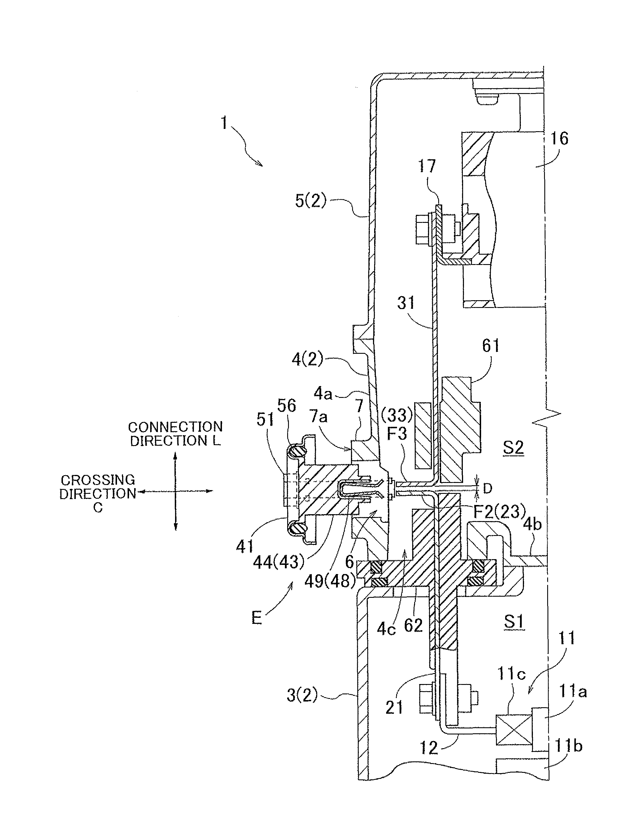
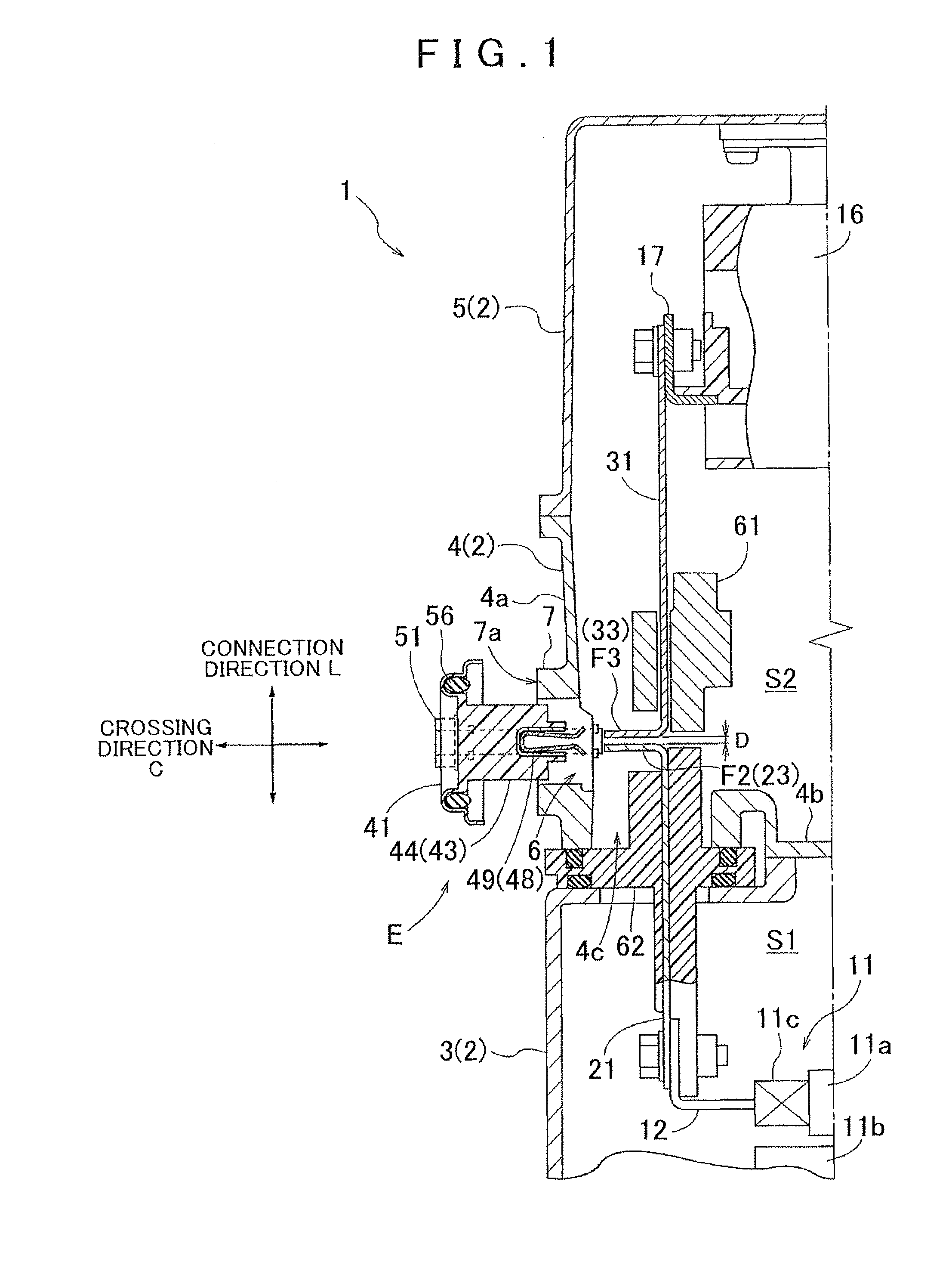
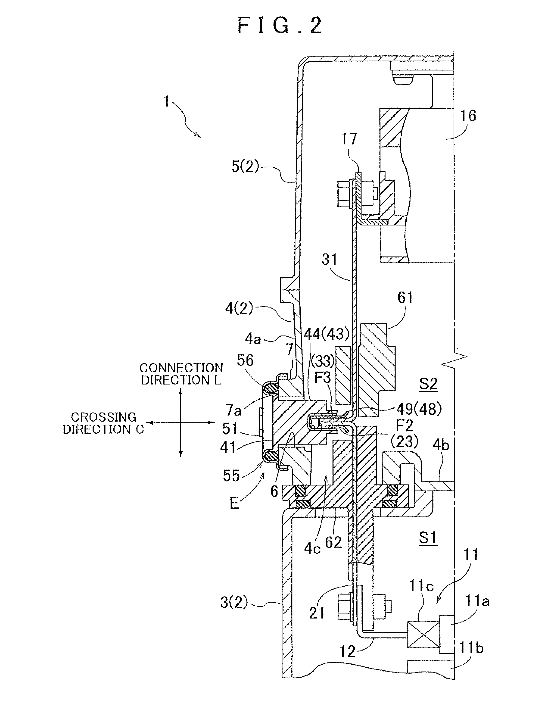
[0040]An embodiment of an electrical connection device according to the present invention will be described below with reference to the accompanying drawings. An electrical connection device E of the present embodiment is applied to a vehicle drive device 1. The electrical connection device E is a device for electrically connecting a rotating electrical machine 11 and an inverter device 16 in a case 2 that accommodates the rotating electrical machine 11 and the inverter device 16. The electrical connection device E of the present embodiment includes: a first bus bar 21 connected to a terminal of the rotating electrical machine 11 (a rotating electrical machine terminal 12) in a state in which the first bus bar 21 is insulated from the case 2; a second bus bar 31 connected to a terminal of the inverter device 16 (an inverter terminal 17) in a state in which the second bus bar 31 is insulated from the case 2; and an insulating connection member 41 for connecting the first bus bar 21 a...


PUM


Abstract

The present invention relates to an electrical connection device that connects a rotating electrical machine and an inverter within a housing. The electrical connection device is configured with a first bus bar connected to a terminal of the rotating electrical machine such that the first bus bar that is insulated from the housing, and a second bus bar that is connected to a terminal of the inverter device such that the second bus bar is also insulated from the housing. An insulating connection member is configured to connect the first bus bar and the second bus bar. The first bus bar and second bus bar are housed within the housing such that they face each other to form a gap between them. The connection member is configured to pass through a wall of the housing so as to electrically connect the first and second bus bars.

Description

INCORPORATION BY REFERENCE[0001]The disclosure of Japanese Patent Application No. 2009-210767 filed on Sep. 11, 2009 including the specification, drawings and abstract is incorporated herein by reference in its entirety.BACKGROUND OF THE INVENTION[0002]The present invention relates to an electrical connection device for electrically connecting a rotating electrical machine and an inverter device in a case that accommodates the rotating electrical machine and the inverter device that controls the rotating electrical machine.DESCRIPTION OF THE RELATED ART[0003]In recent years, an electric vehicle having a rotating electrical machine as a driving source of the vehicle, and a hybrid vehicle having an engine and a rotating electrical machine as a driving source of the vehicle have received attention in terms of fuel consumption, environmental protection, and the like. A drive device for use in such vehicle requires an inverter device for controlling the rotating electrical machine. The r...

Claims


Application Information

Patent Timeline
Patent Type & Authority Patents(United States)
IPC IPC(8): H01R29/00
CPCH01R31/08H02K3/51H02K5/225H01R13/5202H01R2201/10H02K11/0073H02K11/33
Inventor TANAE, MASAHIROUECHI, TATSUYUKIAGATA, HIROMICHIATARASHI, TOMOO
Owner AISIN AW CO LTD
Why Eureka
Try Eureka