
Entropy coding method for coding video prediction residual coefficients

a prediction residual coefficient and coding method technology, applied in the field of image/video coding and decoding technique, can solve the problems of low coding efficiency, single code table cannot adapt well to the variation of local probability distribution, higher computational complexity of arithmetic encoder, etc., and achieves no impact on computational implementation complexity and improved coding efficiency

Active Publication Date: 2011-07-05
INST OF COMPUTING TECH CHINESE ACAD OF SCI
View PDF6 Cites 13 Cited by
  • Summary
  • Abstract
  • Description
  • Claims
  • Application Information

AI Technical Summary

Benefits of technology

"The present invention provides an entropy coding method for video prediction residual coefficients that improves coding efficiency and keeps computational implementation complexity low. The method uses adaptive mechanisms based on local statistical distributions for different macroblock types and level regions. The coding process selects the best matching code table based on the current local probability characteristics. This method fully considers the context information of the coefficients and statistical rules, resulting in improved coding efficiency without impacting computational implementation complexity."

Problems solved by technology

But comparing with the variable length encoder, the arithmetic encoder has higher computational complexity as well as more complicated hardware implementation, in other words, the improvement of coding efficiency is exchanged by higher complexity of the software and hardware.
But the traditional 2D-VLC entropy encoder is coding by obtaining a single code table through global statistic, it has the defect that the single code table can not adapt well to the variation of local probability distributions so that the coding efficiency is lower.

Method used


Image

  • Entropy coding method for coding video prediction residual coefficients
  • Entropy coding method for coding video prediction residual coefficients
  • Entropy coding method for coding video prediction residual coefficients

Examples


Embodiment Construction

[0017]Now, the present invention will be described in details with reference to the accompanying drawings and the preferred embodiments.

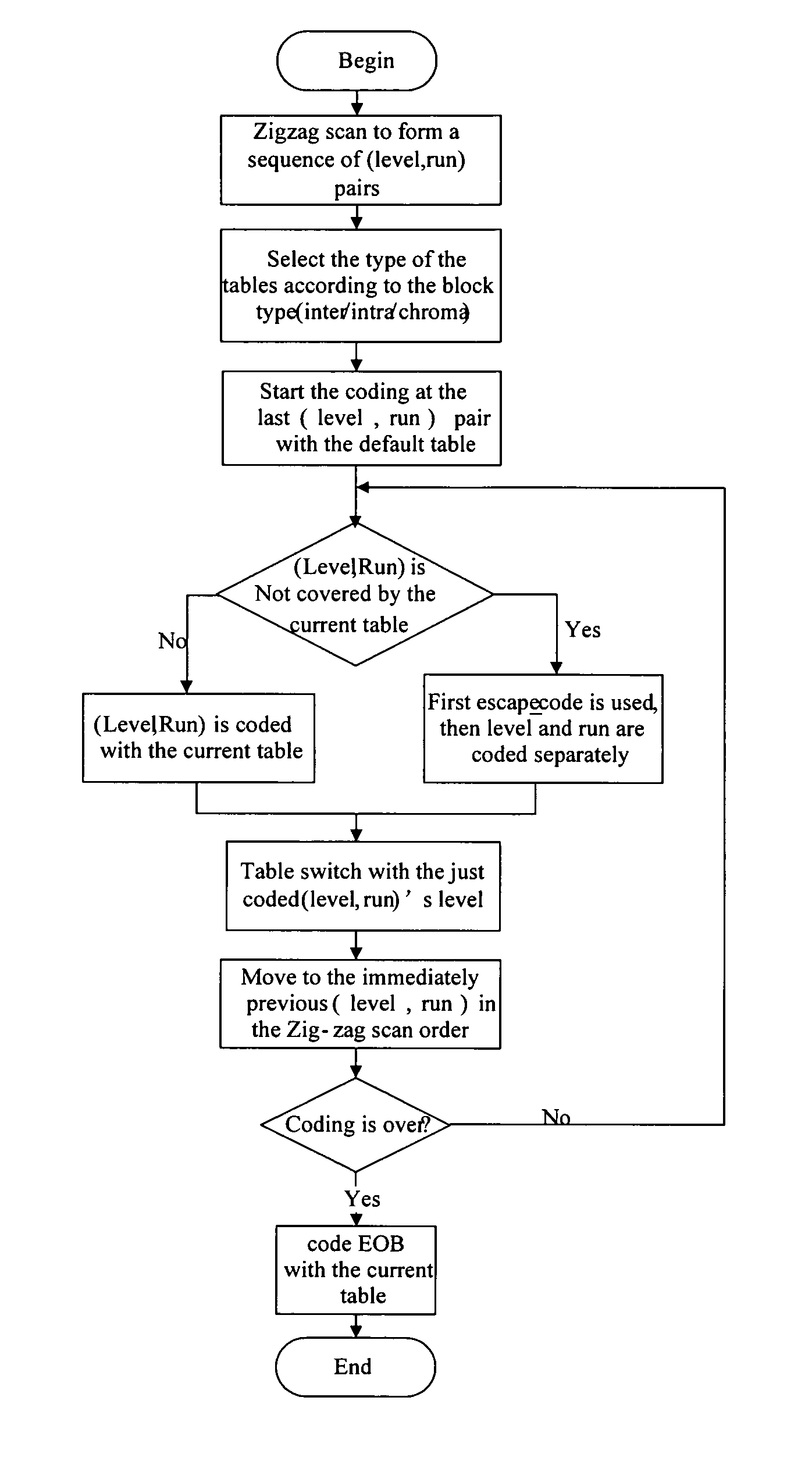
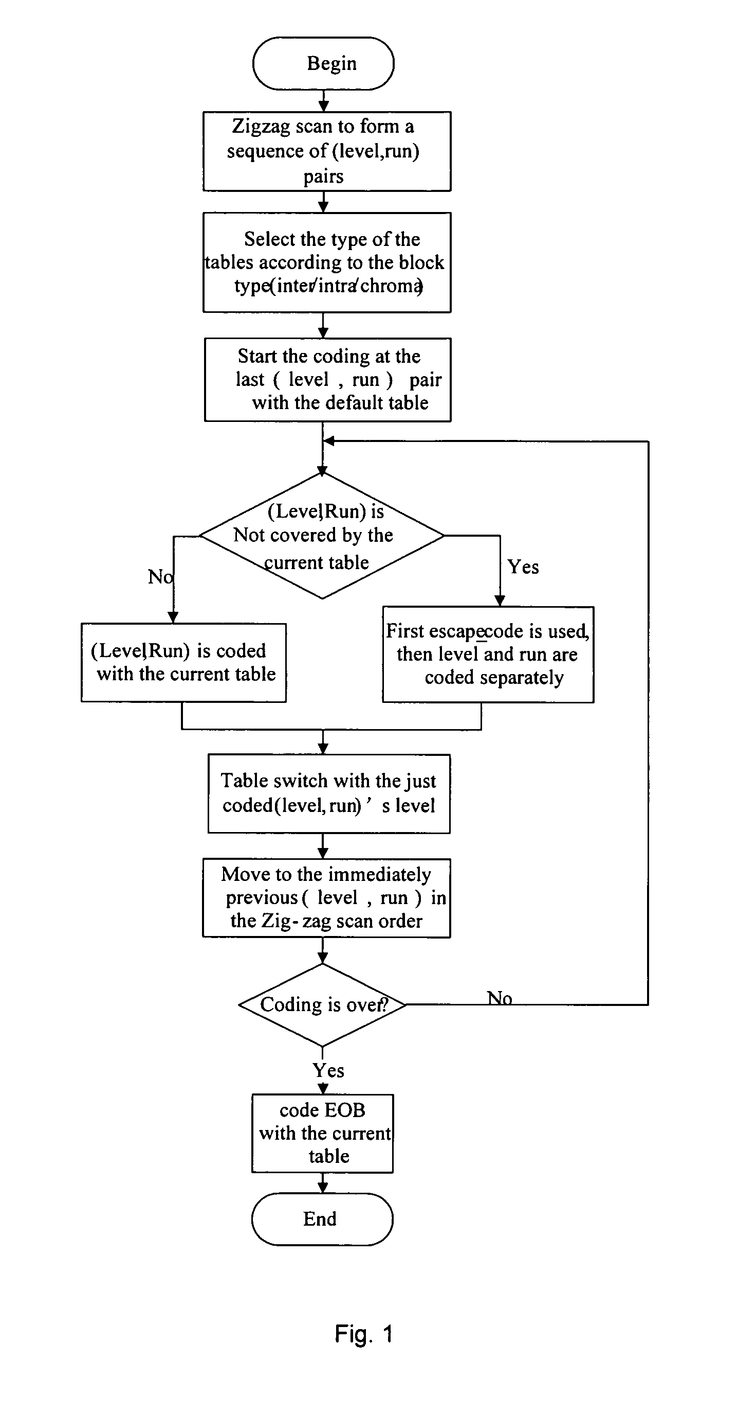
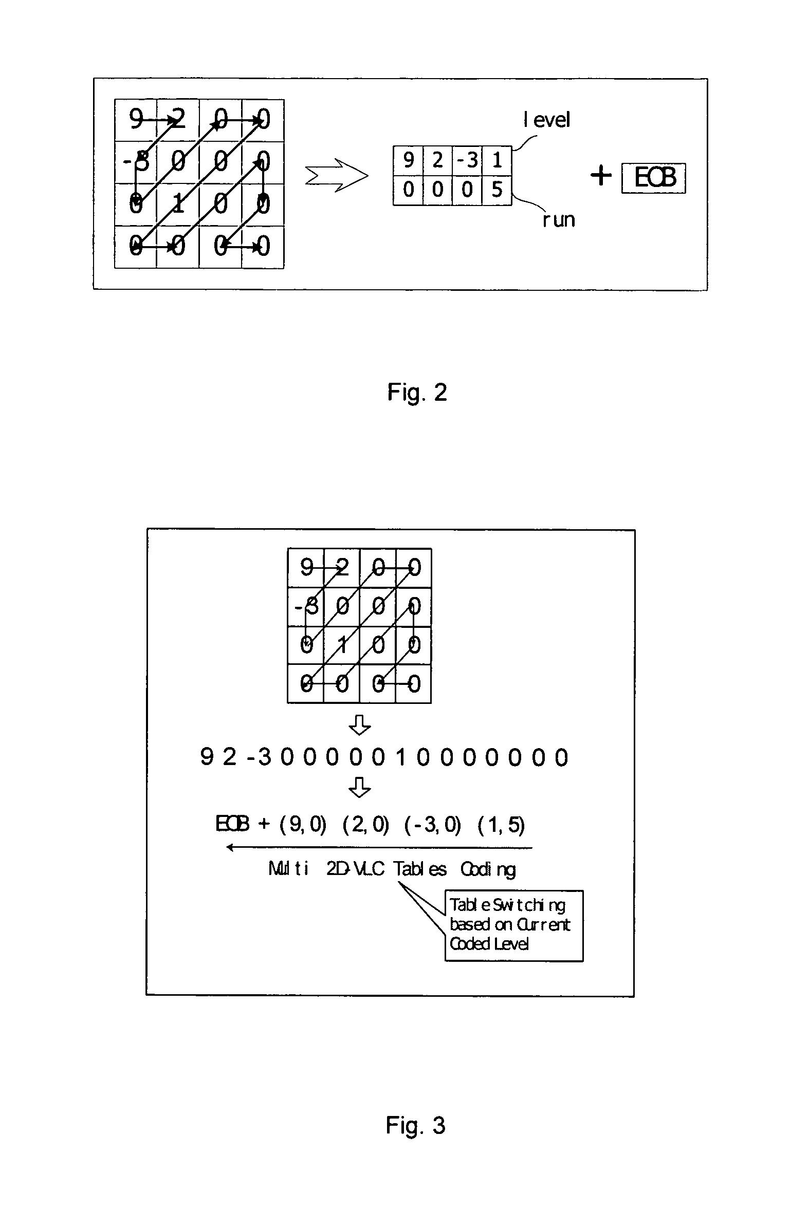
[0018]As shown in FIG. 1 and FIG. 3, the entropy coding method described in the embodiment comprises the following steps:

[0019]step 1: zig-zag scanning an coefficient of an image block to be coded to form a sequence of (level, run) pair;

[0020]step 2: selecting a type of code table for coding a current image block to be coded according to a type of macro block that the image block exists in;

[0021]step 3: coding each (level, run) pair in the sequence of (level, run) pair obtained in step 1;

[0022]step 4: coding a flag of End of BlockEOB.

[0023]In image / video coding, macro block is the basic coding unit. Each macro block contains four 8×8 luminance blocks and two 8×8 chroma blocks, totally six blocks. For entropy coding the prediction residuals, each point in block is a coefficient, and this coefficient indicates the prediction residuals produced from th...


PUM


Abstract

The present invention provides an entropy coding method for coding video prediction residual coefficients, comprising the steps of: firstly, zig-zag scanning coefficients of blocks to be coded to form a sequence of (level, run) pairs; secondly, selecting a type of code table for coding a current image block to be coded according to a type of macro block; then switching and coding each (level, run) pair in the obtained sequence of (level, run) pairs with multiple tables, with the reverse zig-zag scanning order for the coding order of the pairs; at last, coding a flag of End of Block EOB with the current code table. The present invention of an entropy coding method for coding video prediction residual coefficients fully considers the context information and the rules of symbol's conditional probability distribution by designing different tables for different block types and different regions of level. The coding efficiency is improved and no impact to computational implementation complexity is involved.

Description

FIELD OF THE INVENTION[0001]The present invention relates to the image / video coding and decoding technique, and more particularly, to an entropy coding technique method applied in image / video compression and digital audio and video coding for improving coding efficiency and meanwhile keeping low software and hardware computational implementation complexity, which is in the technical field of digital media processing.BACKGROUND OF THE INVENTION[0002]Video coding technique is one of the key techniques in digital media storage and transmission and other applications. The core technique in video coding system consists of prediction coding, transform coding and entropy coding. Entropy coding indicates to encode the syntax elements produced in the process of coding (such as motion vector, block identification, block-based prediction residual, etc.) by exploiting information entropy, which has the function of eliminating the statistical redundancy of data.[0003]In the previous video coding...

Claims


Application Information

Patent Timeline
Patent Type & Authority Patents(United States)
IPC IPC(8): H04N7/12H04N11/02H04N11/04H04N13/02H04N13/04H04N7/50
CPCH04N19/159H04N19/176H04N19/186H04N19/61H04N19/13
Inventor GAO, WENZHAO, DEBINWANG, QIANGMA, SIWEILU, YAN
Owner INST OF COMPUTING TECH CHINESE ACAD OF SCI
Learn More