Image control from composed composite image using HID signal conversion to source image coordinates

a composite image and source image technology, applied in the direction of electric digital data processing, instruments, computing, etc., can solve the problems of reducing the size of objects in the source image on the composed image, and affecting the display of terminal-viewer displays,

Inactive Publication Date: 2011-07-05
KK TOSHIBA
View PDF61 Cites 9 Cited by
  • Summary
  • Abstract
  • Description
  • Claims
  • Application Information

AI Technical Summary

Problems solved by technology

However, if a composed image size is reduced, sizes of objects in a source image on a composed image are also reduced and this may present problems.
However, such small objects may be difficult to be “clicked-on” within terminal-viewer display—especially if the image containing such objects is reduced in size.

Method used


Image

  • Image control from composed composite image using HID signal conversion to source image coordinates
  • Image control from composed composite image using HID signal conversion to source image coordinates
  • Image control from composed composite image using HID signal conversion to source image coordinates

Examples


first exemplary embodiment

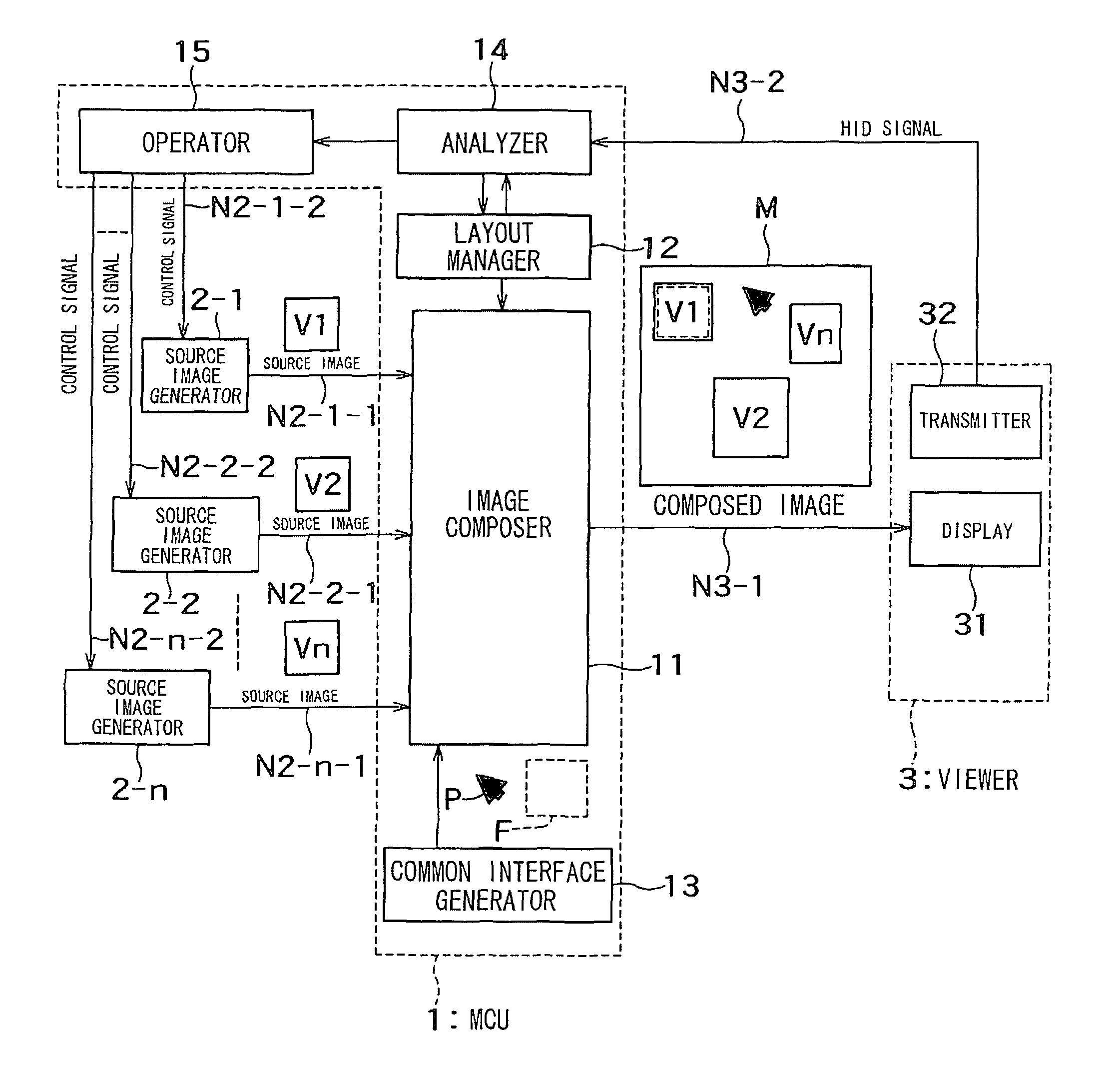
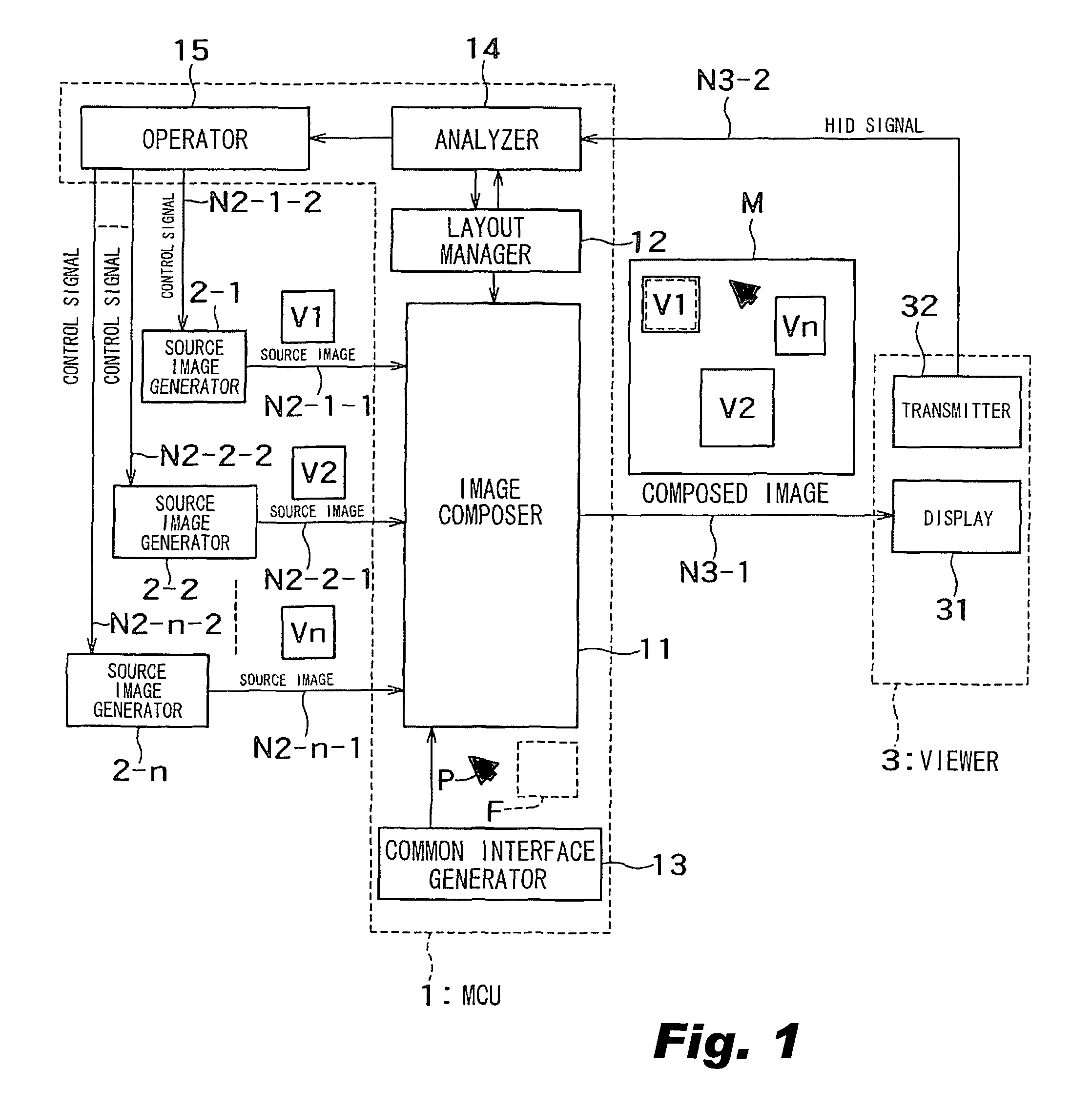
[0049]FIG. 1 illustrates a diagram of an example of a first non-limiting embodiment of a remote-control system.

[0050]A remote-control system includes a plurality of source image generators (numbered from 2-1 to 2-n), a viewer 3, and MCU 1 which communicate with each other through network paths as shown.

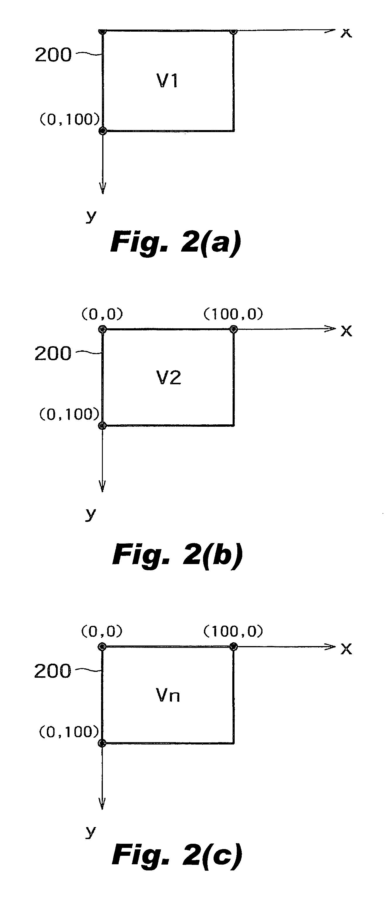
[0051]Source image generators 2-1 and 2-n can be controlled from a remote location through a network. Source image generators 2-1 to 2-n may be PCs. Source image generator 2-1 transmit a source image V1 with a source ID “V1” to MCU 1 through network path N2-1-1. In this embodiment, source image generator 2-1 treats a specification of source image V1 as a normalized value such as 100 percent for each of a horizontal direction x and a vertical direction y shown in FIG. 2(a) as coordinate system 200.

[0052]Source image generator 2-1 controls pointer P on a source image according to a control signal sent from MCU 1. Moreover, source image generator 2-1 detects an event based on the positio...

second embodiment

[0083]An example of a second non-limiting embodiment of a remote-control system is described using FIGS. 21(a) to FIG. 26 (supplementing to the FIGURES described above).

[0084]FIG. 21(a) is an example of layout information stored as layout management table in layout manager 12 in this embodiment. The layout management table has parameters (x′, y′, w′, h′) in addition to the layout management table described in the first embodiment. Those parameters (x′, y′, w′, h′) indicate an operative area.

[0085]The operative area indicates an area to be sent independently of MCU 1. That is, an image in the defined operative area is shown independently on the composed image displayed by viewer 3. In FIG. 21(b), a broken rectangle indicates the operative area. The parameters (x′, y′, w′, h′) are initialized as (0, 0, 100, 100) that indicates the operative area covers all the source image. When the parameters are the initial values, an image in the operative area may not be sent independently of MCU ...

third embodiment

[0098]An example of a third non-limiting embodiment of a remote-control system is described using FIG. 27 to FIG. 29 (supplementing the FIGURES described above).

[0099]FIG. 27 illustrates a schematic diagram of an exemplary third non-limiting embodiment of a remote-control system. In this embodiment, common interface generator 13 uses the control signal, and common interface generator 13 outputs common interface control signals to operator 15. FIG. 28(a) and FIG. 28(b) illustrate composed image M including an image of a software keyboard SK. In FIG. 28(b), the software keyboard SK adjoins source image V1. The image of software keyboard SK includes a plurality of keys.

[0100]If the user controls pointer P onto a key of the software keyboard SK with the mouse and clicks the right button, an HID signal is sent from transmitter 32 of viewer 3 to analyzer 14 of MCU 1. Analyzer 14 analyzes the HID signal sent from viewer 3 and outputs the results of the analysis (e.g., such as the pointer's...


PUM


Abstract

Image control involves receiving source images defined with respect to respective source coordinate systems from source image generators also respectively associated with source IDs. The source images are composed to generate a composite image defined with respect to a composed coordinate system, and the composed image is sent to a viewer which displays the composed image and outputs an HID signal which indicates information defined with respect to the composed coordinate system. A layout manager stores source IDs respectively associated with layout information including position and size of at least one of the source images. An image composer composes the source images according to the layout information. An analyzer analyzes the HID signal for editing layout information stored in the layout manager, and determines a source ID a source image according to the layout information. The HID signal defined with respect to the composed coordinate system is converted to an HID signal defined with respect to the source coordinate system corresponding to the determined source image. An operator then sends the converted HID signal to the source image generator associated with the determined source ID.

Description

CROSS-REFERENCE TO RELATED APPLICATIONS[0001]This application is based upon and claims the benefit of priority under 35 U.S.C. §119 from prior Japanese Patent Application P2005-274472 filed on Sep. 21, 2005, the entire contents of which are hereby incorporated by reference.BACKGROUND[0002]1. Technical Field[0003]This application relates to control of composite images composed of source images by use of HID (Human Interface Device) signals (e.g., from a mouse).[0004]2. Related Art[0005]In one known system, a personal computer (e.g., a “client”) receives image information from a remote computer (e.g., a “server”), and sends signal to the remote computer to request updated image information.[0006]A “Remote Desktop” function is also known which controls a remote computer with a personal computer. Microsoft® Windows® XP has such a “Remote Desktop” function where a personal computer sends operations inputted from local user interfaces (e.g., a mouse and a keyboard), to a remote computer. ...

Claims


Application Information

Patent Timeline
Patent Type & Authority Patents(United States)
IPC IPC(8): G06K9/20G06K9/36G09G5/00G06F3/048
CPCG06F3/1454G09G5/08G09G5/14G09G2310/04
Inventor KAWAMURA, TAKUYAMURAI, SHINYAISE, KOTAROGOTO, MASATAKAYAMAGUCHI, KEIICHI
Owner KK TOSHIBA
Why Eureka
Try Eureka